
In this episode of Flite Test, Josh and Josh talk about how to make your own simple and cheap bomb drop mechanism, while I get to fly Joshe’s EPP FPV.
Bomb drop how to
Leave a comment
Bomb drop Slap Bet!
I challenged Josh Bixler to see which of us that could hit a trampoline with Nerf bombs dropped from airplanes.
I see my self as a pretty good pilot but Josh Bixler is a freaking magician compared to me. I can’t wait to do more challanges!
The Mosquito FPV Cockpit
This is a episode I really enjoyed. The moment hobbyking released their Mosquito I wanted to make it a scale FPV flyer and now with Flite Test help I finally got to do it!
Back in Sweden
I’m back in Sweden after my nearly 3 months long USA adventure. It’s nice to be home but I will sorely miss my friends over the pond.
I had a great time hanging out with the Flite Test guys, making episodes, inventing weird stuff and doing crazy flying. Hopefully I’ll find my way back to the US in not a too distant future.
DIY monopole FPV antennas
The antenna that comes with the 900 and 1300MHz video transmitters usually aren’t any good. In fact they are quite inefficient and due to bad design and build tolerances of certain crucial parts. You can however quite easily improve the efficiency and thus the range of these systems by using a tuned antenna. You can even quite easily build your own!
In this guide I will show how to make two designs.
We will begin with some maths so that you all understand how the antenna length is determine.
First off we need to figure out what the wavelength of our frequency is, and here is a formula to do just that:
?f = c
c = The speed of light = 299 792 458 m/s
? = Wavelength in meters
f = frequency in Hz
To be able to calculate you need to know on what exact frequency your transmitter is operating. For an example; on channel 3 my transmitter is transmitting on 1320 MHz.
And since it is the wavelength we are after we’ll arrange the equation to suit us: (In this example I will be using a frequency of 1200 MHz.)
? = c/f = 299 792 458 / 1200 000 000 = 0,249827048 meters
Now you know how long the wavelength is in meters.
But meters is not a good unit to work with when using such high frequencies, so we’ll take it down to millimeters. Simply take the answer times 1000.
We also need to factor in that the speed of the light in a metal medium is about5% slower than in vacuum. So take the answer times 0,95.
So if you are using an exact frequency of 1200 MHz you end up with an antenna that is 237.34 mm
To sum up the equation:
Full-wave antenna length in mm = 299 792 458/ frequency *1000*0.95
However antennas are rarely made in full-wave due to the fact that it’s hard to get the impedance of the antenna to match the transmitter output. Instead a half or quarter length is chosen.
To simplify things for you I made a couple of simple calculators that you simply put in the frequency in MHz and it outputs the right antenna length for you. These calculators can be found in each of the antenna design parts of this guide.
The half-wave whip antenna

This design utilizes the parts from the original “junk” antenna that comes with most 900/1300Mhz systems. To make this antenna you need 1.5-2mm thick piano wire and a soldering iron. This design is great for those of you that don’t want to modify the transmitter and want the possibility of changing antennas by simply unscrewing it.
Start out by disassembling the stock antenna, which is quite easy, simply unscrew the plastic base.
Now that you know what the length of your antenna should be, cut the piano wire to length and solder it to the signal part of your antenna.
Make sure when making the antenna that you take into account all the parts of the signal wire that is not shielded by ground! Not just the length of the piano wire, but all of the active parts. Otherwise the antenna will be to long and not work well on your frequency.

The range of my system was greatly increased with the new antenna, and the temperature of the video TX was lowered.

This is a good place to start if your want to get started with antenna designing. However this antenna has a drawback; It’s stiff. which means that it will not give way in a crash, which can damage your transmitter.
The quarter-wave lambda antenna
This is my favorite antenna design due to it’s great performance, low weight, ease of build and resilience to crashes.

This antenna is super easy to make, you only need a single-strand wire and a soldering iron. I use a wire that has a 0.5mm diameter copper core(1.4mm with insulation) which is strong enough to not bend during flight but soft enough to bend during a crash.
I recommend soldering this antenna directly to the video transmitters PCB. This reduces weight, improves reliability and increases overall efficiency. However removing the SMA connector requires a bit of soldering skill. Be careful not to damage anything.

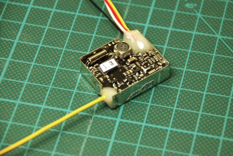
Here is a picture of when I removed a connector from a 300mW 1.3GHz transmitter.
Now you need to cut the wire to the right length, simply calculating the length of the antenna is to use this formula: 71200/frequency = the length in mm

I use channel 4 on my 1.3GHz transmitter (1360MHz) which gives a 52.35mm long antenna. In the picture you can see the (starting from the top) half-wave whip, the stock and the quarter-wave lambda.
I also tied lambda antennas of 1/2-wave and 5/8-wave as well but the 1/4-wave was the best.

Now solder the antenna to the output on the PCB.

I use epoxy to make sure that the antenna doesn’t put any force on the small capacitor which can easily break if left unprotected.

Super light weight, short, low air resistance and efficient. Can you ask for more?
I use the quarter-wave antenna in the videos above. The performance is excellent!
Tuning your antenna
To get the absolute maximum from your DIY antenna you can tune it using nothing more than a multimeter and some time.
So why should you tune your antenna? – To get the best possible range and efficiency out of your transmitter.
So how do you do it?
First off you need to open your video receiver and find the RSSI output (RSSI stands for Receiver Signal Strength Indicator), it’s a signal pin that either increases or decreases its voltage depending on how strong signal the receiver gets from the transmitter. Usually it outputs 5V on full signal and 0.1V with no signal.


On my receiver the RSSI pin was the 7th pin counting from the PCB out towards the antenna output
Now you need to find a place with as little obstacles and interference as possible. An empty field in the middle of nowhere is perfect. Separate the transmitter and receiver by 100 meters or so, less is ok but it’s better with more distance. (A tip is to power of your cellphone when doing the test)
Power up your receiver and transmitter and make sure that both antennas are pointing the same way (either horizontal or vertically), hook up your multimeter with the longest cables you have to make sure that it doesn’t interfere with the reading and so it’s easier to read later on. Do not place the multimeter in between the transmitter and receiver, place it to one side.
For the first test use the stock antenna on the transmitter and move the transmitter away from the receiver until you get a RSSI reading of between 1.5-2V. Up to 3V is ok, but a higher value gives less accuracy later down the test. Check that the picture is good on the receiver, otherwise move the transmitter and receiver closer together.
A pair of binoculars are a good aid when you’re trying to read the multimeter at such great distances.
Now move away a long way from the transmitter and receiver (do not stand in between the transmitter and receiver but rather to one side). Read the multimeter and note on a piece of paper the RSSI value and that it is with the stock antenna. Try to mark the place where you stood when taking the reading as you will want to return to the exact same spot to get the best accuracy during the test.
Now go to the transmitter and replace the antenna with your DIY antenna. The antenna should be about 15mm longer than the calculated length. This is because you will be trimming the antenna down during the test.
Go back to the same spot as when you took you first reading with the stock antenna and write down the antenna length and the RSSI voltage, try to be as accurate as you can.
Now go to the transmitter and trim of 2mm of the antenna (less for more accuracy), go back to the reading spot and write down the RSSI voltage and antenna length.
Repeat this process until your antenna is about 15mm shorter than the calculated length or you see a significant drop in the RSSI voltage.
You should now see what antenna length gave you the best RSSI voltage. Rebuild or make a new antenna that’s exactly that length.
You’re done! You now have a tuned antenna that’s as efficient as it can be.
You don’t “need” to tune your antenna, if you just use the calculated length you still get longer range, but a tuned antenna will be even better.
Good luck and be sure to report back here if you ever try making one of these antennas.