The RCExplorer webshop has permanently closed down. This post is here only for reference. This item is no longer sold.If you wish to make your own, you can download the design files for free from here
We suggest getting the Mateksys PDB FCHUB-W board as a replacement (available on many other webshops). The board offers many great additional features but comes at the cost of being slightly larger. The board will still fit in the Tricopter LR, Baby Tricopter and Bicopter. It might be a tight fit in some cases, but with some cable management, you should be able to get it in there. Here are some example pictures:
Rev4 of the BabyPDB is here! It can now deliver up to 5A continuous current and 20A peak! This new version features 2 BEC output pads allowing for easier soldering of two or more servos. The spacing between that pads has also been increased to make soldering simpler.
Please note:
Built-in voltage regulators on flight controllers are not suitable to power high-performance servos. It can be tempting but those regulators are not made for high peak loading. This might lead to the regulator catastrophically failing and potentially ruining the FC in an event of a shock load to the servo. Instead use an external BEC, like this BabyPDB, that is designed to drive servos.
This is the BabyPDB, a 36x36mm (30.5mm hole spacing) power distribution board with an integrated current sensor and selectable 5/6/8/12V 5A super clean switching BEC.
The board has 4 voltage output pads large enough to allow for easy soldering of ESC power wires and 2 large input voltage pads for big gauge wires from the battery.
The built-in current sensor is great for logging how much power your copter is drawing, but much more interesting is the monitoring of mAh drawn out of the battery. To me this is huge. It allows for a much more accurate way of knowing how much juice is left in your battery. This information can easily be relayed through telemetry to your RC transmitter together with the real-time current draw. Just hook up the Isense pad to the appropriate analogue input pad on your Flight Controller.
The built-in BEC is of the switching type, meaning it’s super efficient and can deliver up to 5A and 20A peak! The output voltage is also easily set to either 5V, 6V, 8V or 12V by bridging 4 different solder pads. The board can easily power 50 5V RGB LED’s without breaking much of a sweat, or you can power FPV gear, servos, charging a GoPro or whatever you fancy.
To make wiring as simple as possible, the board has easily accessible pads for Isense, Vbat out x 2, BEC and ground.
In cleanflight/betaflight/dRonin use current scale 336 to get the correct current value.
Specifications:
The RCExplorer webshop has permanently closed down. This post is here only for reference. This item is no longer sold.If you wish to make your own, you can download the design files for free from here.
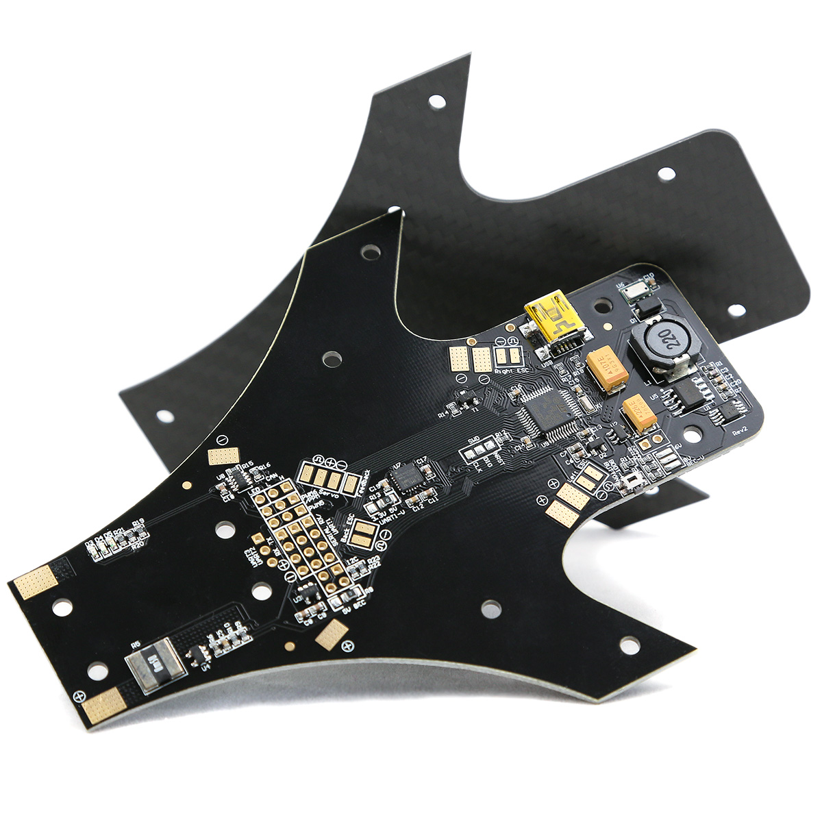
You can now choose the RCExplorer F3FC Tricopter flight controller (with integrated Power Distribution). Designed based on all the feedback we’ve received since the release of the Naze32 frame. This frame has it all; A more powerful processor, 3A switching BEC with selectable 5/6/8V output, no need for a separate power distribution board, pressure sensor, current sensor, low noise gyro/accelerometer connected via SPI and so much more. Read all about it here.
Another huge leap in flight performance is the feedback enabled BMS210 servo. The flight controller now knows where the servo is at all times, which allows it to much more accurately control the tail. The F3FC frame has a dedicated feedback pad straight on the board for very easy hookup. All ESC’s also have surface mount pads straight on the board, which makes for a very clean build and saves a ton of space on the top of the frame.
A carbon fiber bottom board is now also available. Increased stiffness, reduced weight (25% less) and über cool looks.
The Mini Tricopter, a different mini multirotor that packs a punch.
If you’re wondering how to build the copter with the new F3FC check out the Tricopter V4 build video. The build is almost identical.
The Mini Tricopter was designed to utilize parts from the Tricopter V4. It uses the same F3FC frame, servo, tilt mechanism, motor mounts, front spacer and arms (cut to half-length). Which means that you can convert your regular size tricopter to a Mini Tricopter simply by cutting the arms (or getting new pre-cut ones) and screwing on the Mini Tricopter add-on frame. (Warning: cutting carbon fiber is dangerous and may harm your health. Use proper protection if you try it.) Also, don’t forget to downsize the electronics accordingly.
The frame has a built-in adjustable mount for a board-camera with up to a 40x40mm footprint. The angle can be adjusted continuously between 0 and 40° so that you can start out easy and as you progress in your flying, you can add more and more angle to the camera. The camera is well protected by the frame itself as well as the fact that it is held in place by rubber bands, which protects the camera even more during a crash.
The Mini Tricopter also easily carries a GoPro camera with protective housing. The camera is easily mounted on the top of the frame. A GoPro4 session or Mobius/Runcam can be mounted inside of the frame on the Mobius Shelf. This plate can be mounted in two positions to allow for different configurations and camera angles. The supplied silicone camera wedge can be used to fine-tune the angle of the camera.
Flying the Mini Tricopter can be best described as driving an overpowered rear-drive car. It’s not the fastest around the track, but you’ll have the biggest grin on your face when the race is over. The recommended electronics package makes this little beast go almost 160km/h (100mph). The thin arms and smallish body makes it pretty aerodynamically slippery. It requires very little power to cruise at high speeds and it absolutely loves long low-passes with big wide turns. Flips, loops and rolls are quick and crisp thanks to the center of gravity and center of mass being very close to each other.
Transporting the Mini Tricopter is really easy as the arms can be folded back, just like on the larger tricopter. Folded up it’s only 10cm wide and 30cm long (35cm with 6 inch props sticking out straight back) and 8cm tall. The folding design also makes the Mini Tricopter crash-resistant, as the arms may fold back, absorbing energy. The tough “cage” protects the electronics and battery on the inside.
The recommended battery size for the Mini Tricopter is a 4S 1800mAh with a C rating of 35 and upwards. Be sure to check the size of the battery as only batteries up to 110x35x35mm will fit inside of the “cage”. Larger batteries can be fitted on top or below but you’d lose the protection. I also highly recommend using the tricopter frame with integrated F3FC with built-in power distribution board, otherwise, it will get really cramped inside of the “cage”.
To make setup as smooth as possible all PID’s, filters, TPA, tail TPA and such are already tuned for the recommended electronics package. Just click the “Preconfigured Cleanflight Setup” tab above and follow the instructions.
The kit contains:
3 x 1/2 length carbon fiber arms
2 x Motor mounts
1 x Front spacer
1 x Tricopter top board of your choice
1 x Tricopter bottom board of your choice
1 x Tilt mechanism
1 x Servo setup tool
1 x GoPro strap
1 x Battery strap
1 x Zip-ties
1 x Tricopter side plate
8 x 40mm Standoffs
1 x Frame holders
1 x Top tray
1 x Board camera mount + mobius mount
1 x Black rubber bands
1 x Mini tricopter screw pack
1 x Silicone wedge
Recommended electronics:From RCExplorer:
3 x EMAX RS2205 2300KV Motors
3 x Littlebee 30A ESC’s
1 x BMS-210DMH Servo
1 x HQ6x4.5 CCW Propellers
1 x HQ6x4.5 CW Propellers
The parts above can be bought here at a discounted price
More from the RCExplorer store:
A beeper is highly recommended. It makes the setup procedure a lot easier, and it can be used as a lost model alarm, failsafe indicator, low battery and so on.
6mm Wire mesh for protecting the ESC cables
3mm Wire mesh for protecting servo cables
Male to male servo connectors
XT60 battery connector with 5cm cable
From another supplier:
1 x Nanotech 4s 1800mAh 35-70C battery
Alternative: Tattu 1800mAh 45-90C
FPV Setup:
Camera: Sony Effio 800TVL WDR 2.8mm lens
Alternative: PZ0420M 600TVL (without case)
Transmitter: Fatshark 600mW 5.8GHz transmitter
Antennas: Spironets
Video googles: Fatshark Attitude SD
You will also need a RC Transmitter and receiver (Such as the FRsky Taranis). Make sure the receiver supports PPM or SBUS (or serial connection)
This kit requires understanding of electronics, proficient skill in soldering and piloting skill. To fly multirotors, based on cleanflight/betaflight and similar, you will need to give constant stick input. The copter will not fly on it’s own (autonomously) nor will not hold its position in the air in standard configuration. It’s designed to give the best flight experience possible with great flying characteristics. A flight controller of the type this multirotor is using is designed to be felt as little as possible, this in order to let the pilot feel exactly what the copter is doing and to allow for precise flying without the feeling of fighting the flightcontroller.
Although tough, the tricopter is not designed as a beginner platform, but to provide the absolute best flight characteristics and performance. It’s possible to learn to fly on it, but I would recommend that you learn on a smaller platform such as the Eflite Inductrix or on a simulator before taking on a multirotor like this.
It is possible to connect a GPS to this platform, but functionality in the firmware is still under development. It is not a turnkey solution and it will not perform like a DJI Phantom. Autonomous flight is possible but it will require a lot of research, tuning and time to get it to work well.
The RCExplorer webshop has permanently closed down. This post is here only for reference. This item is no longer sold.If you wish to make your own, you can download the design files for free from here
What’s new in the Tricopter V4;
You can now choose the RCExplorer F3FC Tricopter flight controller (with integrated Power Distribution). Designed based on all the feedback we’ve received since the release of the Naze32 frame. This frame has it all; A more powerful processor, 3A switching BEC with selectable 5/6/8V output, no need for a separate power distribution board, pressure sensor, current sensor, low noise gyro/accelerometer connected via SPI and so much more. Read all about it here.
Another huge leap in flight performance is the feedback enabled BMS210 servo. The flight controller now knows where the servo is at all times, which allows it to much more accurately control the tail. The F3FC frame has a dedicated feedback pad straight on the board for very easy hookup. All ESC’s also have surface mount pads straight on the board, which makes for a very clean build and saves a ton of space on the top of the frame.
A carbon fiber bottom board is now also available. Increased stiffness, reduced weight (25% less) and über cool looks.
The camera plate has been redesigned and improved. It is now made from 2mm thick matte 3K carbon fiber. This increases stiffness, which reduces vibrations as well as saves weight (more than 25% lighter). You can now easily mount RunCam2 and GoPro sized cameras.
After many requests the landing gear has now been made taller and with a wider contact area at the bottom. The sharp edge has also been removed. The new landing gear is also mounted with 4 zip-ties which absorbs more energy in a crash. As you will need more zip-ties for the build, the kit now comes with 2 bags (~50 pieces).
The Tricopter V4 is designed to be as light as possible without compromising strength or stiffness. It only weighs 201 grams including Flightcontroller, power distribution, arms, tilt mechanism, motor mounts, screws, landing gear and vibration dampened camera mount! Yet it’s stiffer and more precise than previous versions.
The Tricopter V4 is designed to be easy to build and repair. The landing gear and tilt mechanism are held on using zip-ties, just like in previous versions. These zip-ties acts as “mechanical fuses”, absorbing energy and protecting important pieces in a crash.
Tired of the how easily extruded carbon fiber booms crack and loose their torsion strength, I set out to find a better alternative. Many, many hours of searching I found a factory that could make 10x10mm carbon fiber square tubes to the specifications I was looking for. These woven carbon fiber square tube arms are incredibly stiff, strong and lightweight. The torsion (twisting) strength is unparalleled which results in a crisp and precise flying experience, even with high power setups. Unlike extruded carbon fiber arms, these arms can take abuse without cracking. They are also 33-40% lighter, have more room inside to run wires and are stiffer in all aspects. The kit includes 3 arms with predrilled 3mm holes, so you don’t have to drill it yourself.
The kit also includes a vibration dampening camera/battery tray made from 2mm thick matte 3K twill weave carbon fiber, giving maximum stiffness while reducing weight. The tray is suspended underneath the main body using 4 1.5mm thick crescent-shaped pieces of piano wire.
The wire comes pre-bent (which saves a ton of time and frustration). This vibration dampening system was created specifically for the large flight envelope of the tricopter. The vibrations created by the motors and props spinning only has one way of reaching the camera, and that is down through the thin curved shaped wires. Since the camera plate is stiff, the whole camera tray has to vibrate for the camera to vibrate. With the heavy battery and camera mounted on the tray, a lot of energy is needed to get it moving. The thin and stiff piano wire has a high resonance frequency and low-frequency vibrations will have a hard time to travel down to the camera plate. The small amount of high-frequency vibrations that do make it down has so little energy that they are easily absorbed by the heavy battery and camera. Resulting in buttery smooth footage. The main benefit of this system compared to many soft vibration dampening solutions, is that it doesn’t move or wiggle during fast forward flight or a quick change of direction. This system you can whip around like a maniac and still get perfect video.
Just like the previous tricopter versions, this design is also foldable. This makes transportation easier, but it also help prevent damage in a crash. The arms simply fold back and absorb some of the energy. The arms are held in place by friction, which means that you don’t have to use a tool to fold or unfold, simply grab the arm and push or pull it.
The kit includes the new upgraded version of the tilt mechanism is made from fiberglass reinforced black Nylon which was forged in the fires of Mt. Doom, making it almost indestructible. (It’s the same plastic used by high-end propeller manufacturers). This tilt mechanism is designed to be as simple, precise, light (only 10.6g), durable and with as little air resistance as possible. The design features a spline directly integrated into the part. The recommended servo simply slides right in and gets tightened down by the same screw that is used as the pivot point. Simple, strong and easy to assemble. You can also use any servo with a maximum distance of 8mm from the bottom of the servo body to the bottom of the spline using the “attached servo horn” method, just like on the V2.5 build. (See build-videos on the tilt mechanism product page)
Specifications:
Size unfolded: W600 x L525 x H160mm (with FPV transmitter post)
Size folded: W100 x L500 x H160mm (not counting propellers)
Recommended all up weight: 1100 grams (with GoPro, FPV setup and battery)
Flight time hovering: ~15 minutes (4s 3000mAh)
Flight time Hard flying: ~10 minutes (4s 3000mAh)
Recommended motor size: 28mm outside diameter (up to 33mm fits, 35mm is a little too tight)
Maximum battery size: 40mm tall, 60mm wide, length not really an issue. Slightly larger batteries might fit with minor modifications, like flipping the screws.
The kit contains:
3 x pre-drilled woven carbon fiber arms
1 x Tricopter top board of your choice
1 xTricopter bottom board of your choice
1 x Tilt mechanism
3 x Landing gear (Large)
1 x FPV transmitter post
2 x Motor mounts
1 x Vibration dampening Camera/battery tray (Carbon fiber)
The parts above can be bought here at a discounted priceMore things you might need from the RCExplorer store:A beeperis highly recommended. It makes the setup procedure a lot easier, and it can be used as a lost model alarm, failsafe indicator, low battery and so on.
6mm Wire mesh for protecting the ESC cables
3mm Wire mesh for protecting servo cables
Male to male servo connectors
XT60 5cm pigtail (if you use XT60 connectors on your batteries)
Other things you will need to get up in the air(Given that you have the electronics and parts mentioned above):
A RC Transmitter and receiver (Such as the FRsky Taranis). Make sure the receiver supports PPM or SBUS (or serial connection)
4S LiPo battery with a capacity of 2500-3700mAh. I personally fly on 4S 3200mAh Turnigy A-spec batteries most of the time. (I change the connector to XT60)
If you want to fly FPV:A video transmitter. I personally use the Immersion RC 600mW 5.8GHz (Most countries only allow up to 25mW if you don’t have a HAM licence).
A camera. I personally use a GoPro and fly through the video output on that. You can also use security type camera such as the HS1177.
A viewing device, a screen or video goggles. I personally use the Fatshark attitude HD, but there are much cheaper options.
A video receiver. Mine is built into the goggles. You might need a standalone receiver. Make sure it operates on the same frequency bands as the video transmitter.
Antennas, I use the Immersion RC Spironets
This kit requires an understanding of electronics, proficient skill in soldering and piloting skill. To fly multirotors, based on cleanflight/betaflight and similar, you will need to give constant stick input. The copter will not fly on its own (autonomously) nor will not hold its position in the air in standard configuration. It’s designed to give the best flight experience possible with great flying characteristics. A flight controller of the type this multirotor is using is designed to be felt as little as possible, this in order to let the pilot feel exactly what the copter is doing and to allow for precise flying without the feeling of fighting the flightcontroller.
Although tough, the tricopter is not designed as a beginner platform, but to provide the absolute best flight characteristics and performance. It’s possible to learn to fly on it, but I would recommend that you learn on a smaller platform such as the Eflite Inductrix or on a simulator before taking on a multirotor like this.
It is possible to connect a GPS to this platform, but functionality in the firmware is still under development. It is not a turnkey solution and it will not perform like a DJI Phantom. Autonomous flight is possible but it will require a lot of research, tuning and time to get it to work well.
The RCExplorer webshop has permanently closed down. This post is here only for reference. This item is no longer sold.If you wish to make your own, you can download the design files for free from here
Note that the old 3D printed front spacer will not fit this board. You will need an injection moulded front spacer.
If you want a full tricopter frame, choose between the g10 and carbon fiber bottom boards to go with your F3FC tricopter board. The CF plate is stiffer and weighs about 5g (25%) less, and it looks super fancy too. If you are just upgrading (or repairing) you tricopter, you can choose no bottom board, this way you only get the F3FC Tricoper (top) Board.
This is our new RCExplorer F3FC Tricopter flight controller/PDB frame. Designed based on all the feedback we’ve received since the release of the Naze32 frame. This frame has it all.
Equipped with a SMT32F303CC processor which has a dedicated float point math processor to reduce processor load, freeing up resources to run other fun stuff like GPS (Currently limited functionality in the software), RGB LED’s, compass, blackbox logging, SBUS, OSD and such. This processor also allows for 3 dedicated UART’s which vastly improves connectivity. It’s now possible to run GPS, LED’s, OSD, external compass(via I2C) and SBUS at the same time. The board also has a I2C port and CAN bus which allows for future expandability. It also has a direct connected LED pin for controlling those really cool addressable RGB LED’s.
To save weight and make the build easier and more streamlined, the F3FC tricopter frame is also a power distribution board! Instead of having 2 separate boards and wires going everywhere you now just solder everything to one board and no extra wires between the boards are required. It makes assembling the copter easier, as you don’t have to juggle both boards and arms around at the same time while trying to get everything in place.
That’s not all when it comes to power. The F3FC frame also has a built in 3A switching BEC! This BEC can easily drive the servo, flight controller, OSD, UART devices, RGB LED’s without even running warm. It’s super clean and it also has selectable output voltage of 5V, 6V and 8V, the latter mainly used to power high voltage servos. If you have the BEC set to 8V you can, by bridging two solder points power the UART ports via a built in linear 5V regulator, so that you don’t fry your sensitive 5V expecting devices. The components for the switching BEC are well protected in a crash as they are hidden within the front spacer.
Also mounted inside of the front spacer is a MS5611 high sensitivity, high quality pressure sensor. Together with an external GPS the copter can now do position hold. Mounting the sensor inside of the front spacer keeps it out of direct airflow giving much more accurate readings.
Another great feature is the built in current sensor for monitoring mAh used. To me this is huge. It allows for a much more accurate way of knowing how much juice is left in your battery. This information can easily be relaid through telemetry to your RC transmitter together with the real time current draw and battery voltage (which naturally also is built in to the board).
To give the best flight experience the MPU6000 Gyro/accelerometer chip is used. It’s the least vibration sensitive chip commonly available, which means crisper performance due to lower noise. The MPU6000 is connected through SPI instead of I2C, which allows for much higher update rates. This together with the F3 chips capability of running lower loop times also improves the flight performance greatly.
Another huge leap in flight performance is the feedback enabled BMS210 servo. The flight controller now knows where the servo is at all times, which allows it to much more accurately control the tail. The F3FC frame has a dedicated feedback pad straight on the board for very easy hook up. All ESC’s also have surface mount pads straight on the board, which makes for a very clean build and saves a ton of space on the top of the frame.
To clean up the wiring even more there is now through holes that matches the pin spacing of the beeper. You can now solder the beeper straight to the board without any cables. There is also RAW battery voltage pins to power FPV equipment and such on the top of the frame. No more having to run wires on the side of and then in-between the frames.
Lastly the frame has 2 PWM channels, one of which can be used for PPM receivers. Serial receivers can be plugged into any of the UARTs, but UART1 has a selectable 3.3V/5V selector solder bridge for powering 3.3V spectrum satellites or “normal” receivers.
The F3FC frame is a drop in replacement for the Naze32 frame. You can use it with both the Mini Tricopter and the V4 without any modifications.
90° pinheader + tail tube stopper pinheader are both included in the F3FC Tricotper frame regardless of which (or none) bottom frame is chosen.
A beeper is highly recommended. It makes the setup procedure a lot easier, and it can be used as a lost model alarm, failsafe indicator, low battery and so on.
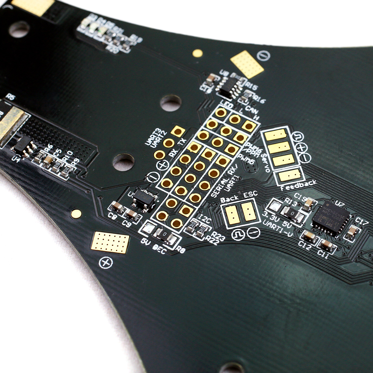
Instructions on how to select UART1 voltage and UART2,3 and PWM voltages:
R8, which have the marking 5V/BEC sets the voltage output on UART2,3 and PWM5+6. If BEC is selected (which is the default) The voltage will be whatever the built in BEC voltage is set to (5V default) If a higher BEC voltage is selected (for instance 8V) the 0 ohm resistor can be moved to the 5V position. This will engage a small LDO voltage regulator that will supply the UART2,3+PWM5,6 with 5V power. The current rating on this regulator is rather small (around 200mA) so it’s extremely important that you don’t try and power LED’s or OSD through any of the PWM ports while using this option. This option is available so that sensitive UART devices that cannot operate on 6 or 8V can still be powered through the board without an external power source.
R13 marked as 3.3V/5V is the voltage selector for UART1, which is used as the Serial RX input. Some receivers can’t handle more than 3.3V (spectrum satellite receiver for instance). If you’re using such a receiver, move the resistor over to the 3.3V position. The 5V option that is the default will give BEC voltage out if R8 (mentioned above) is set at BEC or 5V if R8 is set at 5V. See pictures for reference. (I know this is confusing. Will post a more comprehensive guide to this soon)
Specifications:
Processor: STM32F303CC
Gyro: MPU6000 (8kHz SPI connection)
Pressure sensor: MS5611
USB connector: Mini USB
BEC type: Switching
BEC voltage: Selectable between 5V / 6V / 8V
BEC current: 3A continuous, 5A burst
Material: 1.5mm thick G10/FR4
Dimensions: 130x100x5.5mm
Weigh: ~30 grams
Known bugs;
> Connecting the MinimOSD to UART2 results in strange current readings. Connect either UART1 or 3 and it works as it should. Read more here.
> Also, when using a minimOSD, NEVER EVER connect or disconnect it while either the F3FC or the minimOSD is powered. This can result in the board taking damage. This is true for all FC’s, not just the F3FC. The minimOSD is not kind to UART’s.
The RCExplorer webshop has permanently closed down. This post is here only for reference. This item is no longer sold.If you wish to make your own, you can download the design files for free from here
Made for Bi, Tri and Quad copters.
The F3FC Racing flight controller was designed with 2 things in mind; Performance and cost. To achieve this we chose a 48 pin version STM32F303CC processor and the MPU6000 gyro/accelerometer chip.
The MPU6000 is the least vibration sensitive chip commonly available, which means crisper performance due to lower noise. It is connected through SPI instead of I2C, which allows for up to 8 times higher update rates. This together with the F3 chips capability of running lower loop times vastly improves the flight performance.
Using the 48 pin version of the F303 processor we managed to cut down on cost quite a bit. But you still get 3 UART’s, dedicated USB, 6 PWM’s, I2C, LED port, Current sensor port, Voltage reading and Servo feedback/RSSI. This is achieved by optimising pin connections until we almost went mad, but in the end we did manage it.
The F3FC Racing also has a built in 5V linear voltage regulator. This makes installation easy and clean as no external BEC is needed to power the board or the receiver. However it’s very easy to hook up an external BEC if you would like to power more power hungry things such as a servo, RGB LED’s or a OSD. Just remember to move the little resistor next to the USB connector to “BEC” or you might fry the board! I highly recommend checking out the BabyPDB, which besides being a 36x36mm power distribution board also has built in current sensor and a 3A switching BEC.
The F3FC Racing follows the 36x36mm (30.5mm hole spacing) form factor. It weighs 4.6g. The connection pads are located on the top and bottom edges of the board, just like the popular KISS FC and LUX flight controllers. An easily accessible side mounted boot button is located on the opposite side of the USB connector. This makes entering DFU mode as painless as possible.
This board uses a Mini USB connector instead of the Micro USB commonly used on flight controllers today. This is because the Mini USB is much less likely to break if you accidentally leave the cable in while moving your copter. I know I’m not alone in having destroyed at least one board this way. The F3FC Racing should be able to take a lot more of this kind of abuse.
PPM input is shared with PWM 6. For powering spectrum satellites a 3.3V pad is also available.
The F3FC Racing uses the same architecture as the F3FC tricopter board, which means that it uses the same hex file during flashing.
The F3FC boards are now supported by BetaFlight. Use target “RCExplorerF3” in the firmware flasher tab in the Betaflight configurator.
The F3FC boards are now supported by Cleanflight. Use target “RCExplorerF3” in the firmware flasher tab in the Cleanflight configurator.
Correct signal output for a quadcopters is:
Just like cleanflight/betaflight shows you on the configuration tab.
The correct signal output for a tricopter is:
Pad number 1 = Tail motor
Pad number 2 = Servo
Pad number 3 = Front Right motor
Pad number 4 = Front Left motor
Specifications:
BEC current: 500mA (Not recommended to use more than ~100mA continuously)
Input voltage: 2-6S
Material: 1.5mm thick G10/FR4
Dimensions: 36x36xmm
Hole spacing: 30.5mm
Weight: 4.6 grams
Included in the package:
1 x F3FC Racing board
Don’t forget to get a beeper!
Known bugs;
> Connecting the MinimOSD to UART2 results in strange current readings. Connect either UART1 or 3 and it works as it should. Read more here.
> Also, when using a minimOSD, NEVER EVER connect or disconnect it while either the F3FC or the minimOSD is powered. This can result in the board taking damage. This is true for all FC’s, not just the F3FC. The minimOSD is not kind to UART’s.
The RCExplorer webshop has permanently closed down. This post is here only for reference. This item is no longer sold.If you wish to make your own, you can download the design files for free from here
This upgraded version of the tilt mechanism features injection moulded pieces made from black fiberglass reinforced nylon parts. All parts were forged in the fires of Mt. Doom, making it almost indestructible. (It’s the same plastic used by high-end propeller manufacturers.)
This tilt mechanism is designed to be as simple, precise, light (only 10.6g), durable and with as little air resistance as possible. All parts are made from black fibreglass reinforced nylon for maximum durability. The design features a spline directly integrated into part which enables the recommended servo simply slides right in and gets tightened down by the same screw that is used as the pivot point. Simple, strong and easy to assemble.
The tilt is design around 28mm outside diameter motors with a hole spacing of 16 or 19mm, which is a very common motor size. The tilt can handle motors with a maximum motor size of about 33mm outside diameter. You can squeeze a 35mm motor but it’s not recommended, the bell might rub against the servo. DT750 type motors work well as they stick up high enough not to interfere with the servo.
Designed for 10mm booms the tilt simply attaches using zip-ties that are design to work as “mechanical fuses”, breaking and absorbing energy in a crash, protecting the important parts. It also makes it much easier to repair at the field, just bring some zip-ties.
The tilt is designed around the BMS-210DMH / TGY-210MH servo, which is a really strong and tough servo with great precision. It uses magnetic induction instead of a potentiometer. This means that in a crash, when the servo is subjected to way to much force the magnetic encoder looses track of where the output shaft is and it stops trying to make the servo fight the force, saving the gears. This servo also has a large spline diameter of 6mm which makes it possible to you to 3D print the spline directly into the tilt if you wish to make one yourself. This makes it super strong and slop free. It also uses a M3 servo horn screw, which I took advantage of by designing the tilt to use a 40mm long M3 screw as the pivot axis. This screw simply screws straight through the whole tilt and straight into the servo. The design also works with a other servos directly (list below) or you can use almost any servo as long as it has a maximum distance of 8mm from the bottom of the servo body to the bottom of the spline.
Specifications:
Material: Fiberglass reenforced black nylon
Weight:Complete setup with screw: 10.6g
Top: 5.7 g
Bottom: 2.3 g
Servo holder: 0.8g
Size assembled: L44 x H19 x W28 mm (L69 with recommended servo)
Motor hole mounting: 16-19mm hole spacing (standard motor layout)
Recommended motor size: 28mm outside diameter
Included screws: 1 – 40mm M3 2 mm button head stainless steel hex screw, 1 – Metal spacer, 2 – 6mm M3 2 mm button head stainless steel hex screws, 1 – Black M3 locknut
Servos that fit in the printed spline and the servo holder:
BMS-210DMH – Best choice
TGY-210MH – Best choice
TGY-211MH
BMS-211DMH
BMS-A206
BMS-385DMAX
Turnigy 380MAX
Turnigy 380MG
Servos that should fit with minor modification:
BMS-390DMH – Needs the spacer to be sanded down
Savox SH0261MG – Not tested, but should fit with little to no modification
Savox SH0262MG – Not tested, but should fit with little to no modification
Totally overkill servos – needs a 1mm spacer:
Savox SC1257TG
Savox SH1257MG
Savox SH1250MG
(Align servos of the same size as they are rebranded Savox)
Here is a short list of servos that will work by screwing on the servo horn to the tilt top piece (any servo with a maximum distance of 8mm from the bottom of the servo body to the bottom of the spline will work):
The RCExplorer webshop has permanently closed down. This post is here only for reference. This item is no longer sold. If you wish to modify your own servo to have a feedback wire, please look for a BMS-210 servo elsewhere and then follow the modification instructions found in this build log: https://rcexplorer.se/projects/2016/01/tricopter-v3-5-build/Update: Now with stainless steel output shaft. Even more durable!
The servo that the tilt mechanism is designed around. It’s strong, precise, and has very little slop in the all-metal gearbox, which is supported by dual bearings. It uses a magnetic induction rotary encoder, which is probably one of it’s best features. Apart from being very accurate and very resistant to wear, it can also protect the servo in a crash by “giving way” when the servo is subject to an impact.
We’ve redesigned the original BMS 210 servo to include a feedback wire. This wire is used to accurately determine at which angle the servo is positioned at all times. The wire plugs into the flight controller and the information is used by the TriFlight code to vastly improve the yaw performance of the tricopter. Note: You don’t have to use the servo feedback wire. The servo will work just like any normal servo if you don’t connect the wire.
A replacement gear set for this servo is now available. Don’t forget the T5 screwdriver to be able to disassemble the servo.
Specifications:
Weight: 17.5 grams
Dimensions: 23 x 12 x 25.4 mm
Voltage range: 4.8-6V
Stall current: 1A at 5V
Torque: 4.8V: 3.1 kg/cm, 6.0V: 3.9 kg/cm
Speed: 4.8V: 0.15 sec / 60° (no load), 6.0V: 0.13 sec / 60° (no load)
The RCExplorer webshop has permanently closed down. This post is here only for reference. This item is no longer sold.If you wish to make your own, you can download the design files for free from here
(Please note that above pictures above displays the optional Power distribution board and Kakute F4 flight controller as well as an XT60 pigtail, none of which are included in this product. Camera gear and other electronics/propellers shown in the completed build pictures are not included either.)
A new beast has hatched. Measuring 170mm motor to motor and weighing only 280 grams with electronics and FPV gear! Using almost the same electronics package as the Mini Tricopter (except for 5x4x3 propellers instead of 6×4.5), this means that the Baby Tricopter has a thrust to weight ratio of almost 7 to 1! (running a 4S 1300mAh, 150 gram battery).
The Baby tricopter frame is made from 3mm thick matte twill carbon fiber, which makes it extremely stiff and crazy durable. The unibody design means a lot fewer screws, which saves weight and reduces complexity. Rather than weakening the main frame by cutting big slits for a battery strap, a separate 2mm thick bottom battery plate is used. This also allows you to easily adjust the center of gravity to get the optimal flight performance even when using heavy cameras mounted all the way forward on the top plate. You can also use 2 battery straps on the battery if you wanted to strap it down hard.
The 2mm thick top plate has multiple slits cut for fitting a wide range of cameras, such as a GoPro or a Runcam 2. There is also a hole for mounting the SMA connector from your video transmitter. This greatly reduces the load on your video transmitter during a crash. The top plate has slits for 2 zip ties which are used as receiver antenna mounts. Just slip some heat shrink over the antenna and zip tie and you have a flexible antenna mount that is practically indestructible. These slits are mounted at a 45° angle to reduce the risk of the antenna getting caught in the back prop during a crash.
The baby tricopter uses the standard 30.5mm hole distance for mounting which fits the majority of flight controllers available on the market today. If you don’t already have a fitting flight controller, we’re offering a heavily discounted BabyTricopter + Kakute F4 flight controller + PDB bundle here. In this bundle, our own designs, made to be a perfect match to the Baby Tricopter are included. This features an F3 flight controller with dedicated ports for the servo feedback wire found on our custom BMS-210 servo (which improves the tail performance vastly), and a 30.5mm hole spacing power distribution board with a switching BEC and a built in current sensor, which can be used to get info about the mAh used out of the battery and a whole lot of other features!
The Baby Tricopter uses 30mm standoffs to keep the frame as low profile as possible. This keeps the center of mass closer to the centerline of the thrust, giving better stability and flip/roll performance. It also looks super cool.
The solution for mounting the FPV camera is very simple and straightforward. A recess is cut in the front of the frame to fit the aluminium bracket that comes with HS1177/Runcam swift type cameras. This recess keeps the camera from twisting, which is super annoying and pretty much made the aluminium bracket useless on other frames. This solution is the lightest solution and least complex we’ve tested and it works great.
The Baby Tricopter uses the same indestructible tilt mechanism as the Mini and V4 tricopter. It’s mounted using zip ties, which acts as “mechanical fuses” to help protect the servo and motor in a hard crash.
Included in the kit is a 140mm long crescent-shaped diamond file so that you can smooth the edges of the carbon fiber if you wish to do so. This reduces the chance of a battery strap or zip-tie snapping and it makes the edges smoother and feels nicer to the touch.
It’s highly recommended to use the Baby Tricopter Electronics kit with the supplied PID’s as it can be quite difficult to get the parameters perfect on this small frame. Especially the tail.
Kit includes:
1 x Baby Tricopter 3mm carbon Unibody frame
1 x Baby Tricopter 2mm carbon Top plate
1 x Baby Tricopter 2mm carbon battery plate
1 x 36×36 1mm G10 Video transmitter plate
2 x 15mm wide battery/camera strap
1 x Baby Tricopter screw pack
4 x 30mm aluminium standoffs
1 x Baby tricopter servo setup tool
1 x Tricopter tilt mechanism
1 x bag of zip-ties
Specifications:
Empty weight: 84.8g with tilt mechanism and mounting hardware
Motor to Motor distance: 170mm
Total size of the copter (without props): 200x200x43mm
Thickness CF Unibody frame: 3mm
Thickness CF top and battery plate: 2mm
FC mounting distance: 30.5mm
Recommended all up weight: 280 grams with FPV gear and battery, Easily carries a GoPro.
Recommended motor size: 2204-2206
Recommended Battery: 4S 1300mAh
Other things needed:Baby Tricopter Electronics kit
Kakute F4 Racing Flight Controller
Power distribution board
XT60 pigtail
A beeper
An RC Transmitter and receiver (Such as the FRsky Taranis). Make sure the receiver supports PPM or SBUS (or serial connection)
4S LiPo battery with a capacity of 1000-2200mAh. I personally fly on 4S 1300mAh 65C batteries.
If you want to fly FPV:A video transmitter. I personally use the TBS Unify Pro 5.8GHz (Most countries only allow up to 25mW if you don’t have a HAM licence).
A camera. I personally use the HS1177.
A viewing device – a screen or video goggles. I personally use the Fatshark attitude HD, there are much cheaper options.
A video receiver. Mine is built into the goggles. You might need a standalone receiver. Make sure it operates on the same frequency bands as the video transmitter.
Antennas, I use the TBS Triumph.
Watch this great step by step build and setup video by Andy RC. It shows how to set up the newer betaflight based Triflight version 0.7 beta 2.
This kit requires an understanding of electronics, proficient skill in soldering and piloting skill. To fly multirotors, based on cleanflight/betaflight and similar, you will need to give constant stick input. The copter will not fly on its own (autonomously) nor will not hold its position in the air in standard configuration. It’s designed to give the best flight experience possible with great flying characteristics. A flight controller of the type this multirotor is using is designed to be felt as little as possible, this in order to let the pilot feel exactly what the copter is doing and to allow for precise flying without the feeling of fighting the flightcontroller.
Although tough, the tricopter is not designed as a beginner platform, but to provide the absolute best flight characteristics and performance. It’s possible to learn to fly on it, but I would recommend that you learn on a smaller platform such as the Eflite Inductrix or on a simulator before taking on a multirotor like this.
It is possible to connect a GPS to this platform, but functionality in the firmware is still under development. It is not a turnkey solution and it will not perform like a DJI Phantom. Autonomous flight is possible but it will require a lot of research, tuning and time to get it to work well.
Are you looking for a challenge? Then you’ve come to the right place!
*Electronics not included
Say hello to the RCExplorer Bicopter. Yes, Bi as in 2! This copter only uses 2 motors and 2 propellers to generate lift.
Pretty cool eh? But you don’t get much control with just 2 motors, you need something more; Servos! Pitch and yaw are controlled by tilting the motors in either the same or opposite direction.
*Electronics not included
This makes the RCExplorer Bicopter look freaking fantastic flying around. In full forward flight with the motors at full tilt, it’s reminiscent of the V22 Osprey.
The RCExplorer Bicopter is designed to look as badass as possible, and I think we succeeded. The frame is entirely made from high-quality 3k twill weave matte finish carbon fiber. This makes the RCExplorer Bicopter frame lightweight, durable and worth drooling over.
*Electronics not included
Just picture yourself rolling up your flying buddies and whipping this thing out. Guaranteed instant +10 to street cred and coolness (guarantee not guaranteed).
The sharp-looking backend not only looks like a formidable stabbing weapon, it also makes the copter fly better. The weight is distributed more evenly and the leverage arm is longer, which should make the pitch axis more stable.
*Electronics not included
This thing is a challenge. Are you up for it?
This thing is not like a crazy locked in quadcopter that obeys your every command. No, you have to fly this the way it wants to be flown. It is not easy and it will take some getting used to. Tuning is tricky, fiddly and might vary greatly depending on the electronics used (Pre-tuned starting PID’s available for the recommended electronics kit.). You can get yourself into weird situations very quickly and it currently doesn’t like flying backwards.
What it does like is forward flight (both slow and flat out), lazy turns and hovering (as long as it’s not drifting backwards). You can do tricks as well, but be ready for some fun recovery manoeuvres. It is a very different flying experience compared to most other crafts.
*Electronics not included
*Electronics not included
Building the RCExplorer Bicopter is also a bit of a challenge. Designed to be as cool looking as possible lead to some awkward spaces. Cable management skills will for sure make things easier, but you will probably still want to curse us a couple of times during the build.
Update: The Bicopter now comes with a 5mm flat arm instead of a 10x10mm square tube arm. The build should be nearly identical as this arm is mounted in the same way as the square arm shown in the build video.
The notches on the end of the arms help prevent the tilt mechanisms from sliding on the arms after a crash.
The new flat arm leaves more space for wires to enter the frame, making the build a bit easier.
Please use this connection schematic rather than the one you see in the video
Once you’ve gotten through the build, mastered the flying and tamed the beast, the payoff is a freaking badass looking sci-fi machine howling down low across the field with tilted rotors.Only you can decide if that is worth it or not.
*Electronics not included
Can we improve it?
Currently, the RCExplorer Bicopter is running stock betaflight firmware. This firmware is designed mainly for quadcopters and very little improvements have been done to other aircraft in that code. The handling of servos on both tricopters and bicopters is far from ideal. Luckily we have a very awesome community on this site. A community that has been able to improve on the tricopter code so much that it went from feeling like flying a wet eel to a homing missile. Together we can explore if it’s possible to improve the flight envelope of bicopters as well. Jump over to the forums and share your experience. Note: It is highly recommended to use the special position feedback servos. They will most likely increase performance vastly once the feature is implemented in the firmware.
*Electronics not included
*Electronics not included
*Electronics not included
*Electronics not included
What’s in the box?
Everything shown in this picture is included:
1 FC Plate
1 Grill Plate
1 Side plates (pair)
4 Top plates
1 Top Wings (set)
1 Bottom Wings (set)
1 Bicopter Arm
1 Bicopter battery plate
1 Bicopter Screw Pack
4 40 mm black standoffs
2 Tilt mechanisms
1 Servo setup tool
1 Zip ties (bag)
2 Thin battery/GoPro straps
Specs:
Length: 238mm
Width: 270mm
Hight: 75mm
Empty weight: ~165g
All up weight (with electronics kit, without battery): ~285g
CF parts thickness: 1.5mm
Recommended battery size: 4S 1300mAh
It is highly recommended to use the special position feedback servos we provide. They will most likely increase performance vastly once the feature is implemented in the firmware.
Recommended electronics:
We recommend the Bicopter electronics kit.
It comes with motors, ESC’s, cables, propellers and the highly recommended special position feedback servo.
This will be the setup we base our PID’s around. Other electronics will most likely need a different tune.
Then you all you need is:
1 Kakute F4 Flight Controller
1 Power distribution board
1 XT60 pigtail (Or a matching power connector to whatever you already use)1 Beeper
A 4S LiPo battery with a capacity of around 1300mAh.
An RC Transmitter and receiver (Such as the FRsky Taranis). Make sure the receiver supports PPM or SBUS (or serial connection of some kind)
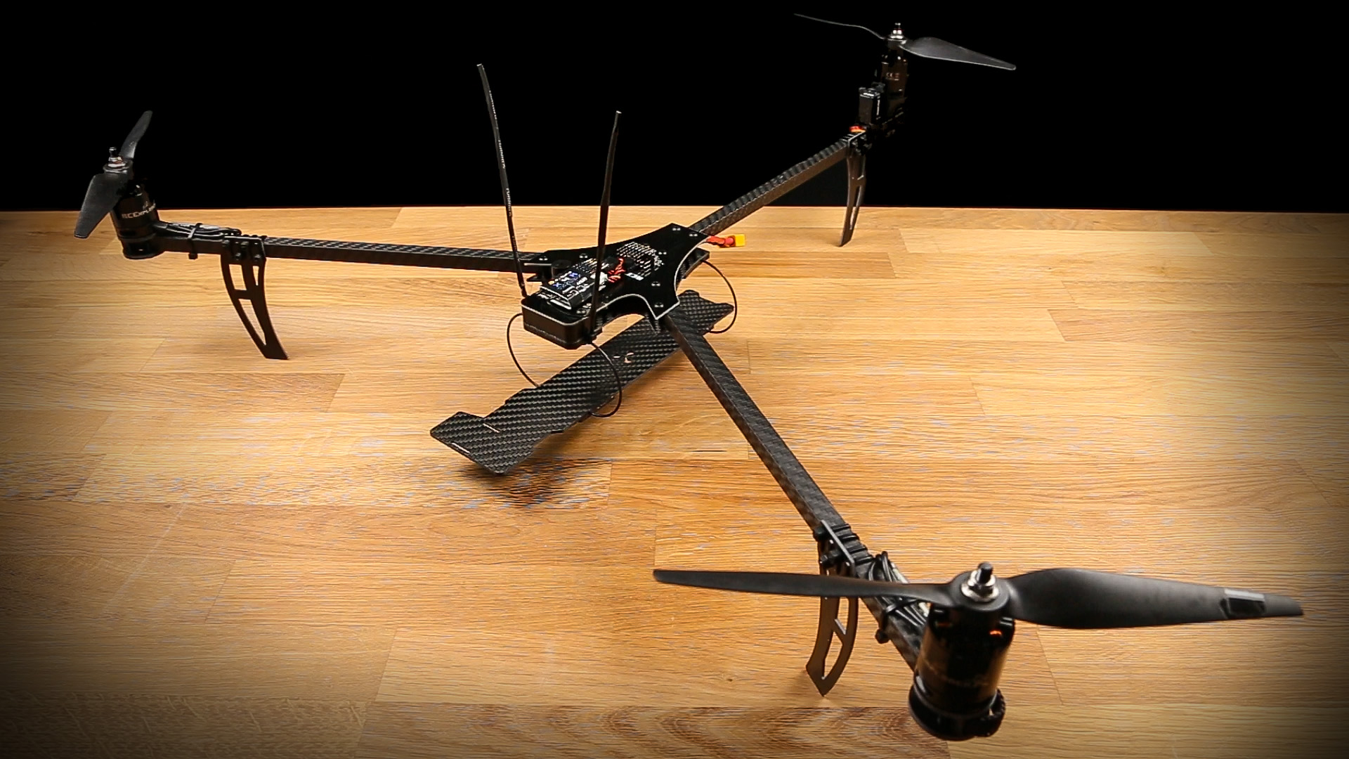
The RCExplorer webshop has permanently closed down. This post is here only for reference.If you wish to make your own, you can download the design files for free from hereThis is the Tricopter LR (Long Range). Efficient, nimble, transportable and with long flight time, those were the goals when designing this copter. The low drag and long flight time make this copter very well suited for long range explorative flying.There are few things more exhilarating than flying high and far. Navigating by landmarks, flying above the clouds at sunset, diving down mountains and exploring the surroundings is the name of the game*. The thrill of knowing it’s only your own navigation skills that will get your copter back is very addictive, not to mention the incredible views you get to experience.
*Might be subject to rules and regulations in your country. You should always make sure to follow any local rules!
The Tricopter LR ticks all the boxes when it comes to this type of flying. The frame is lightweight, allowing for more battery capacity to be carried at the same final weight. It also swings up to 8″ propellers, which give close to double the prop area compared to a 5″ quad and almost the same disk area as 7″ quad! With only 3 arms, less lift is wasted, due to less air-blocking arm area. The LR also uses narrower (but thicker) arms to reduce that drag even more, without sacrificing stiffness.QUIET!
Not a fan of the screaming 5″ quads? The tricopter LR is very quiet compared to smaller crafts. The larger, slower spinning propellers generate a lot less noise. They are also more efficient, generating the same amount of lift at a lower RPM. Instead of that 5″ high pitched screaming, which draws attention and disturb others, the LR makes a low tone “wosh” sound that doesn’t carry far and is much less annoying to be around.Lightweight
Thanks to the slimmed down design, the tricopter LR frame only weighs 112 grams. That is almost half of the already lightweight Tricopter V4! Less weight means more battery carrying capacity, which means longer flight times!
The kit includes a tilt mechanism made from fiberglass reinforced black Nylon which was forged in the fires of Mt. Doom (ok, maybe not), making it almost indestructible. It’s the same plastic used by high-end propeller manufacturers! This tilt mechanism is designed to give minimum air resistance and be as simple, precise, light (only 10.6g) and durable as possible. The design features a spline directly integrated into the part. The recommended servo simply slides right in and gets tightened down by the same screw that is used as the pivot point. Simple, strong, and easy to assemble.
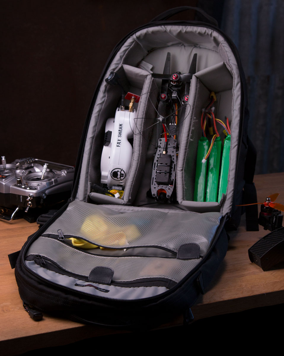
Easy to transport
Despite having large 8″ props the Tricopter LR is easily transported. If you pull on the front arms they fold back making the whole copter super compact! Small enough to fit in a backpack with plenty of room left over for all your other gear. The best part is that no tools are needed for folding and unfolding! This makes transportation easier, and it also helps prevent damage in a crash. The arms can simply fold back and absorb some of the energy on impact.Plenty of space
There is extra space in the frame for all kinds of electronics. Mounting a large video TX, GPS, full-size receiver, and such is possible without the frustration and Tetris playing associated with many other builds.
*Electronics not included
The Tricopter LR uses the common 30.5mm mounting hole pattern standard for flight controllers, which opens up the possibility to use a wide variety of flight controllers and power distribution boards. We recommend using the BabyPDB and KakuteF4 V2, as they are both designed to work with Tricopters. (Please note that not all flight controllers work with tricopters. If you’re thinking of getting another flight controller, research if it’s compatible with tricopters first. Never use a built-in 5V regulator in any flight controller to power a servo!)
Build videoSetup video:Video capabilities
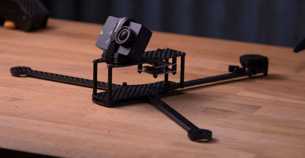
Capturing beautiful imagery is a huge part of flying long range. That is why we went to great lengths to make sure that no props are visible in the image (when using the recommended setup). This was no small feat on a copter swinging 8″ propellers on a compact frame but we did manage it! Now you can share gorgeous HD video without distracting props or obstructions. The LR is designed to carry both the smaller GoPro session cube style cameras as well as full-size GoPros even without a 3D printed housing.
The Tricopter LR also has space for a separate FPV camera, which can be mounted using the lightweight bracket that is included with most modern FPV cameras. Mount the camera with the lens tilted to your flying style. With the lens tilted up, the setup allows for fast forward flight with the horizon still in the middle of the frame.Long flight time
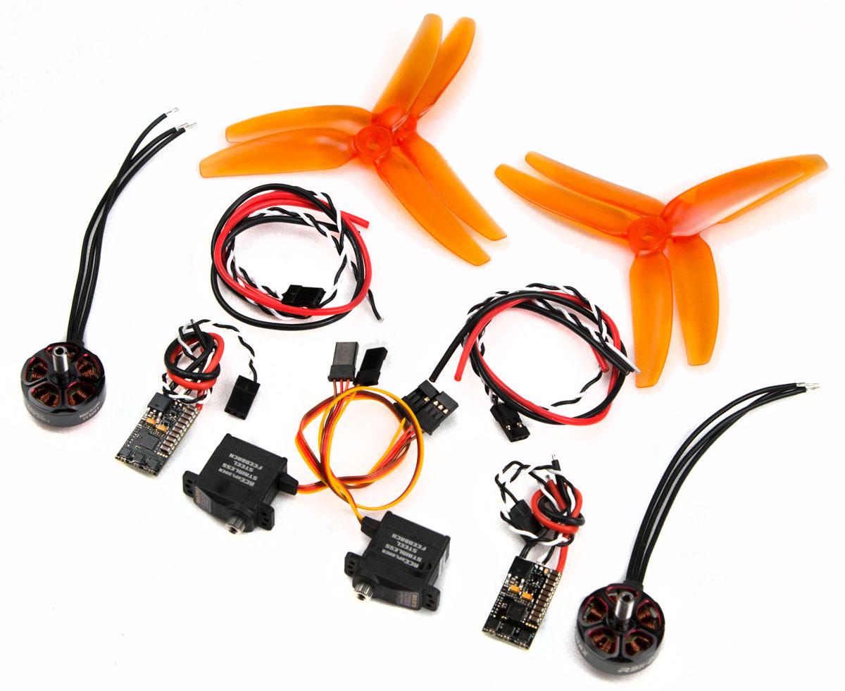
Thanks to the recent advances in motor technology we now have smaller, lightweight, more powerful and efficient brushless motors. The 6S battery trend on mini quads has lead manufacturers to make lower kV motors in the same small form factor. The Tricopter LR is designed to take full advantage of this, using 3S (for long flight time) or 4S (for bonkers flying). The recommended 1600kV 2207 motors weigh less than half of the motors previously used on the Tricopter V4, yet they are more efficient. That is even more weight saved that can go towards battery capacity, which together with the higher efficiency of the motors equals more flight time. We have put together a super efficient electronics pack for the Tricopter LR that, with the right battery and a light build, makes it possible to achieve over an hour of hovering flight time!
Tricopter LR with 2 5200mAh 3S batteriesWhy a tricopter?
The short answer is: “Swooshiness”.
Tricopters have a special feel to them. On quadcopters, yaw is generated by speeding up one pair of the same spinning direction propellers and slowing down the opposite rotating propellers. The difference in rotational force causes the copter to turn very precisely around its middle axis. Yaw motion on a tricopter is different. It’s generated by mechanically changing the angle of the back motor left or right. The back motor literally pushes the tail to the right or left. This creates some interesting flight characteristics. It basically makes the copter feel more like an airplane. The tail acts as a rudder would. On an airplane, if you input a rudder command the plane will try to turn rather than just spin the plane around its own yaw axis. A tricopter kind of makes coordinated turns as you input yaw, just like a plane would. If you’re traveling fast forward and input yaw on a quadcopter it will continue in the exact direction it was going before, but now you’re looking in a different direction. A tricopter would try to ease into a turn. This is what makes it feel more like an airplane, smoother, more fluid, more organic, less like a machine. “Swooshy” in other words.
Specifications:
Empty frame weight: 112 grams
Motor to Motor distance: 350/310mm
Size unfolded: W380 x L290 x H54mm
Size folded: W65 x L290 x H54mm (not counting propellers)
Recommended all up weight: 650-1100 grams
Flight time hovering: ~40 minutes (3s 5200mAh)
The kit contains:
2 x Front arms
1 x Back arms
1 xTop plate
1 x Middle plate
1 x Bottom plate
1 x Tilt mechanism
3 x Thin Battery/GoPro strap
1 x 12° Camera angle Silicone Wedge
1 x Bag of Zip-ties
1 x Screw pack
4 x 40mm aluminium standoffs
1 x Servo setup tool
Recommended electronics
We recommend the Tricopter LR electronics kit.
It comes with motors, ESC’s, propellers and the highly recommended special position feedback servo.
This will be the setup we base our PID’s around. Other electronics will most likely need a different tune.
Then all you need is:
– 1 Kakute F4 Flight Controller
– 1 Power distribution board
– 1 XT60 pigtail (Or a matching power connector to whatever you already use)– 1 Beeper
– A 3S LiPo battery with a capacity of around 2200-6000mAh (or a 4S for bonkers flying instead of maximum flight time)
– An RC Transmitter and receiver (Such as the FRsky Taranis). Make sure the receiver supports SBUS (or serial connection of some kind)
This kit requires an understanding of electronics, proficient skill in soldering, and piloting skill. To fly multirotors, based on cleanflight/betaflight and similar, you will need to give constant stick input. The copter will not fly on its own (autonomously), nor will not hold its position in the air in standard configuration. It’s designed to give the best flight experience possible with great flying characteristics. A flight controller of the type this multirotor is using is designed to be felt as little as possible, this in order to let the pilot feel exactly what the copter is doing and to allow for precise flying without the feeling of fighting the flight controller.
Although tough, the tricopter is not designed as a beginner platform, but to provide the absolute best flight characteristics and performance. It’s possible to learn to fly on it, but I would recommend that you learn on a smaller platform such as the Eflite Inductrix or on a simulator before taking on a multirotor like this.
It is possible to connect a GPS to this platform, but functionality in the firmware is still under development. It is not a turnkey solution and it will not perform like a DJI Phantom. Autonomous flight is possible but it will require you to do a lot of research, tuning, and spend a lot of time to get it to work well.


 We suggest getting the Mateksys PDB FCHUB-W board as a replacement (available on many other webshops). The board offers many great additional features but comes at the cost of being slightly larger. The board will still fit in the Tricopter LR, Baby Tricopter and Bicopter. It might be a tight fit in some cases, but with some cable management, you should be able to get it in there. Here are some example pictures:


 Rev4 of the BabyPDB is here! It can now deliver up to 5A continuous current and 20A peak! This new version features 2 BEC output pads allowing for easier soldering of two or more servos. The spacing between that pads has also been increased to make soldering simpler.
Please note:
Built-in voltage regulators on flight controllers are not suitable to power high-performance servos. It can be tempting but those regulators are not made for high peak loading. This might lead to the regulator catastrophically failing and potentially ruining the FC in an event of a shock load to the servo. Instead use an external BEC, like this BabyPDB, that is designed to drive servos.
This is the BabyPDB, a 36x36mm (30.5mm hole spacing) power distribution board with an integrated current sensor and selectable 5/6/8/12V 5A super clean switching BEC.
The board has 4 voltage output pads large enough to allow for easy soldering of ESC power wires and 2 large input voltage pads for big gauge wires from the battery.
The built-in current sensor is great for logging how much power your copter is drawing, but much more interesting is the monitoring of mAh drawn out of the battery. To me this is huge. It allows for a much more accurate way of knowing how much juice is left in your battery. This information can easily be relayed through telemetry to your RC transmitter together with the real-time current draw. Just hook up the Isense pad to the appropriate analogue input pad on your Flight Controller.
The built-in BEC is of the switching type, meaning it’s super efficient and can deliver up to 5A and 20A peak! The output voltage is also easily set to either 5V, 6V, 8V or 12V by bridging 4 different solder pads. The board can easily power 50 5V RGB LED’s without breaking much of a sweat, or you can power FPV gear, servos, charging a GoPro or whatever you fancy.
To make wiring as simple as possible, the board has easily accessible pads for Isense, Vbat out x 2, BEC and ground.
In cleanflight/betaflight/dRonin use current scale 336 to get the correct current value.
Specifications:
Rev4 of the BabyPDB is here! It can now deliver up to 5A continuous current and 20A peak! This new version features 2 BEC output pads allowing for easier soldering of two or more servos. The spacing between that pads has also been increased to make soldering simpler.
Please note:
Built-in voltage regulators on flight controllers are not suitable to power high-performance servos. It can be tempting but those regulators are not made for high peak loading. This might lead to the regulator catastrophically failing and potentially ruining the FC in an event of a shock load to the servo. Instead use an external BEC, like this BabyPDB, that is designed to drive servos.
This is the BabyPDB, a 36x36mm (30.5mm hole spacing) power distribution board with an integrated current sensor and selectable 5/6/8/12V 5A super clean switching BEC.
The board has 4 voltage output pads large enough to allow for easy soldering of ESC power wires and 2 large input voltage pads for big gauge wires from the battery.
The built-in current sensor is great for logging how much power your copter is drawing, but much more interesting is the monitoring of mAh drawn out of the battery. To me this is huge. It allows for a much more accurate way of knowing how much juice is left in your battery. This information can easily be relayed through telemetry to your RC transmitter together with the real-time current draw. Just hook up the Isense pad to the appropriate analogue input pad on your Flight Controller.
The built-in BEC is of the switching type, meaning it’s super efficient and can deliver up to 5A and 20A peak! The output voltage is also easily set to either 5V, 6V, 8V or 12V by bridging 4 different solder pads. The board can easily power 50 5V RGB LED’s without breaking much of a sweat, or you can power FPV gear, servos, charging a GoPro or whatever you fancy.
To make wiring as simple as possible, the board has easily accessible pads for Isense, Vbat out x 2, BEC and ground.
In cleanflight/betaflight/dRonin use current scale 336 to get the correct current value.
Specifications:


 The frame has a built-in adjustable mount for a board-camera with up to a 40x40mm footprint. The angle can be adjusted continuously between 0 and 40° so that you can start out easy and as you progress in your flying, you can add more and more angle to the camera. The camera is well protected by the frame itself as well as the fact that it is held in place by rubber bands, which protects the camera even more during a crash.
The Mini Tricopter also easily carries a GoPro camera with protective housing. The camera is easily mounted on the top of the frame. A GoPro4 session or Mobius/Runcam can be mounted inside of the frame on the Mobius Shelf. This plate can be mounted in two positions to allow for different configurations and camera angles. The supplied silicone camera wedge can be used to fine-tune the angle of the camera.
Flying the Mini Tricopter can be best described as driving an overpowered rear-drive car. It’s not the fastest around the track, but you’ll have the biggest grin on your face when the race is over. The recommended electronics package makes this little beast go almost 160km/h (100mph). The thin arms and smallish body makes it pretty aerodynamically slippery. It requires very little power to cruise at high speeds and it absolutely loves long low-passes with big wide turns. Flips, loops and rolls are quick and crisp thanks to the center of gravity and center of mass being very close to each other.
Transporting the Mini Tricopter is really easy as the arms can be folded back, just like on the larger tricopter. Folded up it’s only 10cm wide and 30cm long (35cm with 6 inch props sticking out straight back) and 8cm tall. The folding design also makes the Mini Tricopter crash-resistant, as the arms may fold back, absorbing energy. The tough “cage” protects the electronics and battery on the inside.
The recommended battery size for the Mini Tricopter is a 4S 1800mAh with a C rating of 35 and upwards. Be sure to check the size of the battery as only batteries up to 110x35x35mm will fit inside of the “cage”. Larger batteries can be fitted on top or below but you’d lose the protection. I also highly recommend using the tricopter frame with integrated F3FC with built-in power distribution board, otherwise, it will get really cramped inside of the “cage”.
To make setup as smooth as possible all PID’s, filters, TPA, tail TPA and such are already tuned for the recommended electronics package. Just click the “Preconfigured Cleanflight Setup” tab above and follow the instructions.
The kit contains:
The frame has a built-in adjustable mount for a board-camera with up to a 40x40mm footprint. The angle can be adjusted continuously between 0 and 40° so that you can start out easy and as you progress in your flying, you can add more and more angle to the camera. The camera is well protected by the frame itself as well as the fact that it is held in place by rubber bands, which protects the camera even more during a crash.
The Mini Tricopter also easily carries a GoPro camera with protective housing. The camera is easily mounted on the top of the frame. A GoPro4 session or Mobius/Runcam can be mounted inside of the frame on the Mobius Shelf. This plate can be mounted in two positions to allow for different configurations and camera angles. The supplied silicone camera wedge can be used to fine-tune the angle of the camera.
Flying the Mini Tricopter can be best described as driving an overpowered rear-drive car. It’s not the fastest around the track, but you’ll have the biggest grin on your face when the race is over. The recommended electronics package makes this little beast go almost 160km/h (100mph). The thin arms and smallish body makes it pretty aerodynamically slippery. It requires very little power to cruise at high speeds and it absolutely loves long low-passes with big wide turns. Flips, loops and rolls are quick and crisp thanks to the center of gravity and center of mass being very close to each other.
Transporting the Mini Tricopter is really easy as the arms can be folded back, just like on the larger tricopter. Folded up it’s only 10cm wide and 30cm long (35cm with 6 inch props sticking out straight back) and 8cm tall. The folding design also makes the Mini Tricopter crash-resistant, as the arms may fold back, absorbing energy. The tough “cage” protects the electronics and battery on the inside.
The recommended battery size for the Mini Tricopter is a 4S 1800mAh with a C rating of 35 and upwards. Be sure to check the size of the battery as only batteries up to 110x35x35mm will fit inside of the “cage”. Larger batteries can be fitted on top or below but you’d lose the protection. I also highly recommend using the tricopter frame with integrated F3FC with built-in power distribution board, otherwise, it will get really cramped inside of the “cage”.
To make setup as smooth as possible all PID’s, filters, TPA, tail TPA and such are already tuned for the recommended electronics package. Just click the “Preconfigured Cleanflight Setup” tab above and follow the instructions.
The kit contains:


 What’s new in the Tricopter V4;
 The camera plate has been redesigned and improved. It is now made from 2mm thick matte 3K carbon fiber. This increases stiffness, which reduces vibrations as well as saves weight (more than 25% lighter). You can now easily mount RunCam2 and GoPro sized cameras.
 After many requests the landing gear has now been made taller and with a wider contact area at the bottom. The sharp edge has also been removed. The new landing gear is also mounted with 4 zip-ties which absorbs more energy in a crash. As you will need more zip-ties for the build, the kit now comes with 2 bags (~50 pieces).
The Tricopter V4 is designed to be as light as possible without compromising strength or stiffness. It only weighs 201 grams including Flightcontroller, power distribution, arms, tilt mechanism, motor mounts, screws, landing gear and vibration dampened camera mount! Yet it’s stiffer and more precise than previous versions.
The Tricopter V4 is designed to be easy to build and repair. The landing gear and tilt mechanism are held on using zip-ties, just like in previous versions. These zip-ties acts as “mechanical fuses”, absorbing energy and protecting important pieces in a crash.
Tired of the how easily extruded carbon fiber booms crack and loose their torsion strength, I set out to find a better alternative. Many, many hours of searching I found a factory that could make 10x10mm carbon fiber square tubes to the specifications I was looking for. These woven carbon fiber square tube arms are incredibly stiff, strong and lightweight. The torsion (twisting) strength is unparalleled which results in a crisp and precise flying experience, even with high power setups. Unlike extruded carbon fiber arms, these arms can take abuse without cracking. They are also 33-40% lighter, have more room inside to run wires and are stiffer in all aspects. The kit includes 3 arms with predrilled 3mm holes, so you don’t have to drill it yourself.
The kit also includes a vibration dampening camera/battery tray made from 2mm thick matte 3K twill weave carbon fiber, giving maximum stiffness while reducing weight. The tray is suspended underneath the main body using 4 1.5mm thick crescent-shaped pieces of piano wire.
The wire comes pre-bent (which saves a ton of time and frustration). This vibration dampening system was created specifically for the large flight envelope of the tricopter. The vibrations created by the motors and props spinning only has one way of reaching the camera, and that is down through the thin curved shaped wires. Since the camera plate is stiff, the whole camera tray has to vibrate for the camera to vibrate. With the heavy battery and camera mounted on the tray, a lot of energy is needed to get it moving. The thin and stiff piano wire has a high resonance frequency and low-frequency vibrations will have a hard time to travel down to the camera plate. The small amount of high-frequency vibrations that do make it down has so little energy that they are easily absorbed by the heavy battery and camera. Resulting in buttery smooth footage. The main benefit of this system compared to many soft vibration dampening solutions, is that it doesn’t move or wiggle during fast forward flight or a quick change of direction. This system you can whip around like a maniac and still get perfect video.
Just like the previous tricopter versions, this design is also foldable. This makes transportation easier, but it also help prevent damage in a crash. The arms simply fold back and absorb some of the energy. The arms are held in place by friction, which means that you don’t have to use a tool to fold or unfold, simply grab the arm and push or pull it.
The kit includes the new upgraded version of the tilt mechanism is made from fiberglass reinforced black Nylon which was forged in the fires of Mt. Doom, making it almost indestructible. (It’s the same plastic used by high-end propeller manufacturers). This tilt mechanism is designed to be as simple, precise, light (only 10.6g), durable and with as little air resistance as possible. The design features a spline directly integrated into the part. The recommended servo simply slides right in and gets tightened down by the same screw that is used as the pivot point. Simple, strong and easy to assemble. You can also use any servo with a maximum distance of 8mm from the bottom of the servo body to the bottom of the spline using the “attached servo horn” method, just like on the V2.5 build. (See build-videos on the tilt mechanism product page)
Specifications:
After many requests the landing gear has now been made taller and with a wider contact area at the bottom. The sharp edge has also been removed. The new landing gear is also mounted with 4 zip-ties which absorbs more energy in a crash. As you will need more zip-ties for the build, the kit now comes with 2 bags (~50 pieces).
The Tricopter V4 is designed to be as light as possible without compromising strength or stiffness. It only weighs 201 grams including Flightcontroller, power distribution, arms, tilt mechanism, motor mounts, screws, landing gear and vibration dampened camera mount! Yet it’s stiffer and more precise than previous versions.
The Tricopter V4 is designed to be easy to build and repair. The landing gear and tilt mechanism are held on using zip-ties, just like in previous versions. These zip-ties acts as “mechanical fuses”, absorbing energy and protecting important pieces in a crash.
Tired of the how easily extruded carbon fiber booms crack and loose their torsion strength, I set out to find a better alternative. Many, many hours of searching I found a factory that could make 10x10mm carbon fiber square tubes to the specifications I was looking for. These woven carbon fiber square tube arms are incredibly stiff, strong and lightweight. The torsion (twisting) strength is unparalleled which results in a crisp and precise flying experience, even with high power setups. Unlike extruded carbon fiber arms, these arms can take abuse without cracking. They are also 33-40% lighter, have more room inside to run wires and are stiffer in all aspects. The kit includes 3 arms with predrilled 3mm holes, so you don’t have to drill it yourself.
The kit also includes a vibration dampening camera/battery tray made from 2mm thick matte 3K twill weave carbon fiber, giving maximum stiffness while reducing weight. The tray is suspended underneath the main body using 4 1.5mm thick crescent-shaped pieces of piano wire.
The wire comes pre-bent (which saves a ton of time and frustration). This vibration dampening system was created specifically for the large flight envelope of the tricopter. The vibrations created by the motors and props spinning only has one way of reaching the camera, and that is down through the thin curved shaped wires. Since the camera plate is stiff, the whole camera tray has to vibrate for the camera to vibrate. With the heavy battery and camera mounted on the tray, a lot of energy is needed to get it moving. The thin and stiff piano wire has a high resonance frequency and low-frequency vibrations will have a hard time to travel down to the camera plate. The small amount of high-frequency vibrations that do make it down has so little energy that they are easily absorbed by the heavy battery and camera. Resulting in buttery smooth footage. The main benefit of this system compared to many soft vibration dampening solutions, is that it doesn’t move or wiggle during fast forward flight or a quick change of direction. This system you can whip around like a maniac and still get perfect video.
Just like the previous tricopter versions, this design is also foldable. This makes transportation easier, but it also help prevent damage in a crash. The arms simply fold back and absorb some of the energy. The arms are held in place by friction, which means that you don’t have to use a tool to fold or unfold, simply grab the arm and push or pull it.
The kit includes the new upgraded version of the tilt mechanism is made from fiberglass reinforced black Nylon which was forged in the fires of Mt. Doom, making it almost indestructible. (It’s the same plastic used by high-end propeller manufacturers). This tilt mechanism is designed to be as simple, precise, light (only 10.6g), durable and with as little air resistance as possible. The design features a spline directly integrated into the part. The recommended servo simply slides right in and gets tightened down by the same screw that is used as the pivot point. Simple, strong and easy to assemble. You can also use any servo with a maximum distance of 8mm from the bottom of the servo body to the bottom of the spline using the “attached servo horn” method, just like on the V2.5 build. (See build-videos on the tilt mechanism product page)
Specifications:


 Note that the old 3D printed front spacer will not fit this board. You will need an injection moulded front spacer.
If you want a full tricopter frame, choose between the g10 and carbon fiber bottom boards to go with your F3FC tricopter board. The CF plate is stiffer and weighs about 5g (25%) less, and it looks super fancy too. If you are just upgrading (or repairing) you tricopter, you can choose no bottom board, this way you only get the F3FC Tricoper (top) Board.
This is our new RCExplorer F3FC Tricopter flight controller/PDB frame. Designed based on all the feedback we’ve received since the release of the Naze32 frame. This frame has it all.
Equipped with a SMT32F303CC processor which has a dedicated float point math processor to reduce processor load, freeing up resources to run other fun stuff like GPS (Currently limited functionality in the software), RGB LED’s, compass, blackbox logging, SBUS, OSD and such. This processor also allows for 3 dedicated UART’s which vastly improves connectivity. It’s now possible to run GPS, LED’s, OSD, external compass(via I2C) and SBUS at the same time. The board also has a I2C port and CAN bus which allows for future expandability. It also has a direct connected LED pin for controlling those really cool addressable RGB LED’s.
To save weight and make the build easier and more streamlined, the F3FC tricopter frame is also a power distribution board! Instead of having 2 separate boards and wires going everywhere you now just solder everything to one board and no extra wires between the boards are required. It makes assembling the copter easier, as you don’t have to juggle both boards and arms around at the same time while trying to get everything in place.
That’s not all when it comes to power. The F3FC frame also has a built in 3A switching BEC! This BEC can easily drive the servo, flight controller, OSD, UART devices, RGB LED’s without even running warm. It’s super clean and it also has selectable output voltage of 5V, 6V and 8V, the latter mainly used to power high voltage servos. If you have the BEC set to 8V you can, by bridging two solder points power the UART ports via a built in linear 5V regulator, so that you don’t fry your sensitive 5V expecting devices. The components for the switching BEC are well protected in a crash as they are hidden within the front spacer.
Also mounted inside of the front spacer is a MS5611 high sensitivity, high quality pressure sensor. Together with an external GPS the copter can now do position hold. Mounting the sensor inside of the front spacer keeps it out of direct airflow giving much more accurate readings.
Another great feature is the built in current sensor for monitoring mAh used. To me this is huge. It allows for a much more accurate way of knowing how much juice is left in your battery. This information can easily be relaid through telemetry to your RC transmitter together with the real time current draw and battery voltage (which naturally also is built in to the board).
To give the best flight experience the MPU6000 Gyro/accelerometer chip is used. It’s the least vibration sensitive chip commonly available, which means crisper performance due to lower noise. The MPU6000 is connected through SPI instead of I2C, which allows for much higher update rates. This together with the F3 chips capability of running lower loop times also improves the flight performance greatly.
Another huge leap in flight performance is the feedback enabled BMS210 servo. The flight controller now knows where the servo is at all times, which allows it to much more accurately control the tail. The F3FC frame has a dedicated feedback pad straight on the board for very easy hook up. All ESC’s also have surface mount pads straight on the board, which makes for a very clean build and saves a ton of space on the top of the frame.
To clean up the wiring even more there is now through holes that matches the pin spacing of the beeper. You can now solder the beeper straight to the board without any cables. There is also RAW battery voltage pins to power FPV equipment and such on the top of the frame. No more having to run wires on the side of and then in-between the frames.
Lastly the frame has 2 PWM channels, one of which can be used for PPM receivers. Serial receivers can be plugged into any of the UARTs, but UART1 has a selectable 3.3V/5V selector solder bridge for powering 3.3V spectrum satellites or “normal” receivers.
The F3FC frame is a drop in replacement for the Naze32 frame. You can use it with both the Mini Tricopter and the V4 without any modifications.
90° pinheader + tail tube stopper pinheader are both included in the F3FC Tricotper frame regardless of which (or none) bottom frame is chosen.
A beeper is highly recommended. It makes the setup procedure a lot easier, and it can be used as a lost model alarm, failsafe indicator, low battery and so on.
Instructions on how to select UART1 voltage and UART2,3 and PWM voltages:
R8, which have the marking 5V/BEC sets the voltage output on UART2,3 and PWM5+6. If BEC is selected (which is the default) The voltage will be whatever the built in BEC voltage is set to (5V default) If a higher BEC voltage is selected (for instance 8V) the 0 ohm resistor can be moved to the 5V position. This will engage a small LDO voltage regulator that will supply the UART2,3+PWM5,6 with 5V power. The current rating on this regulator is rather small (around 200mA) so it’s extremely important that you don’t try and power LED’s or OSD through any of the PWM ports while using this option. This option is available so that sensitive UART devices that cannot operate on 6 or 8V can still be powered through the board without an external power source.
R13 marked as 3.3V/5V is the voltage selector for UART1, which is used as the Serial RX input. Some receivers can’t handle more than 3.3V (spectrum satellite receiver for instance). If you’re using such a receiver, move the resistor over to the 3.3V position. The 5V option that is the default will give BEC voltage out if R8 (mentioned above) is set at BEC or 5V if R8 is set at 5V. See pictures for reference. (I know this is confusing. Will post a more comprehensive guide to this soon)
Specifications:
Note that the old 3D printed front spacer will not fit this board. You will need an injection moulded front spacer.
If you want a full tricopter frame, choose between the g10 and carbon fiber bottom boards to go with your F3FC tricopter board. The CF plate is stiffer and weighs about 5g (25%) less, and it looks super fancy too. If you are just upgrading (or repairing) you tricopter, you can choose no bottom board, this way you only get the F3FC Tricoper (top) Board.
This is our new RCExplorer F3FC Tricopter flight controller/PDB frame. Designed based on all the feedback we’ve received since the release of the Naze32 frame. This frame has it all.
Equipped with a SMT32F303CC processor which has a dedicated float point math processor to reduce processor load, freeing up resources to run other fun stuff like GPS (Currently limited functionality in the software), RGB LED’s, compass, blackbox logging, SBUS, OSD and such. This processor also allows for 3 dedicated UART’s which vastly improves connectivity. It’s now possible to run GPS, LED’s, OSD, external compass(via I2C) and SBUS at the same time. The board also has a I2C port and CAN bus which allows for future expandability. It also has a direct connected LED pin for controlling those really cool addressable RGB LED’s.
To save weight and make the build easier and more streamlined, the F3FC tricopter frame is also a power distribution board! Instead of having 2 separate boards and wires going everywhere you now just solder everything to one board and no extra wires between the boards are required. It makes assembling the copter easier, as you don’t have to juggle both boards and arms around at the same time while trying to get everything in place.
That’s not all when it comes to power. The F3FC frame also has a built in 3A switching BEC! This BEC can easily drive the servo, flight controller, OSD, UART devices, RGB LED’s without even running warm. It’s super clean and it also has selectable output voltage of 5V, 6V and 8V, the latter mainly used to power high voltage servos. If you have the BEC set to 8V you can, by bridging two solder points power the UART ports via a built in linear 5V regulator, so that you don’t fry your sensitive 5V expecting devices. The components for the switching BEC are well protected in a crash as they are hidden within the front spacer.
Also mounted inside of the front spacer is a MS5611 high sensitivity, high quality pressure sensor. Together with an external GPS the copter can now do position hold. Mounting the sensor inside of the front spacer keeps it out of direct airflow giving much more accurate readings.
Another great feature is the built in current sensor for monitoring mAh used. To me this is huge. It allows for a much more accurate way of knowing how much juice is left in your battery. This information can easily be relaid through telemetry to your RC transmitter together with the real time current draw and battery voltage (which naturally also is built in to the board).
To give the best flight experience the MPU6000 Gyro/accelerometer chip is used. It’s the least vibration sensitive chip commonly available, which means crisper performance due to lower noise. The MPU6000 is connected through SPI instead of I2C, which allows for much higher update rates. This together with the F3 chips capability of running lower loop times also improves the flight performance greatly.
Another huge leap in flight performance is the feedback enabled BMS210 servo. The flight controller now knows where the servo is at all times, which allows it to much more accurately control the tail. The F3FC frame has a dedicated feedback pad straight on the board for very easy hook up. All ESC’s also have surface mount pads straight on the board, which makes for a very clean build and saves a ton of space on the top of the frame.
To clean up the wiring even more there is now through holes that matches the pin spacing of the beeper. You can now solder the beeper straight to the board without any cables. There is also RAW battery voltage pins to power FPV equipment and such on the top of the frame. No more having to run wires on the side of and then in-between the frames.
Lastly the frame has 2 PWM channels, one of which can be used for PPM receivers. Serial receivers can be plugged into any of the UARTs, but UART1 has a selectable 3.3V/5V selector solder bridge for powering 3.3V spectrum satellites or “normal” receivers.
The F3FC frame is a drop in replacement for the Naze32 frame. You can use it with both the Mini Tricopter and the V4 without any modifications.
90° pinheader + tail tube stopper pinheader are both included in the F3FC Tricotper frame regardless of which (or none) bottom frame is chosen.
A beeper is highly recommended. It makes the setup procedure a lot easier, and it can be used as a lost model alarm, failsafe indicator, low battery and so on.
Instructions on how to select UART1 voltage and UART2,3 and PWM voltages:
R8, which have the marking 5V/BEC sets the voltage output on UART2,3 and PWM5+6. If BEC is selected (which is the default) The voltage will be whatever the built in BEC voltage is set to (5V default) If a higher BEC voltage is selected (for instance 8V) the 0 ohm resistor can be moved to the 5V position. This will engage a small LDO voltage regulator that will supply the UART2,3+PWM5,6 with 5V power. The current rating on this regulator is rather small (around 200mA) so it’s extremely important that you don’t try and power LED’s or OSD through any of the PWM ports while using this option. This option is available so that sensitive UART devices that cannot operate on 6 or 8V can still be powered through the board without an external power source.
R13 marked as 3.3V/5V is the voltage selector for UART1, which is used as the Serial RX input. Some receivers can’t handle more than 3.3V (spectrum satellite receiver for instance). If you’re using such a receiver, move the resistor over to the 3.3V position. The 5V option that is the default will give BEC voltage out if R8 (mentioned above) is set at BEC or 5V if R8 is set at 5V. See pictures for reference. (I know this is confusing. Will post a more comprehensive guide to this soon)
Specifications:
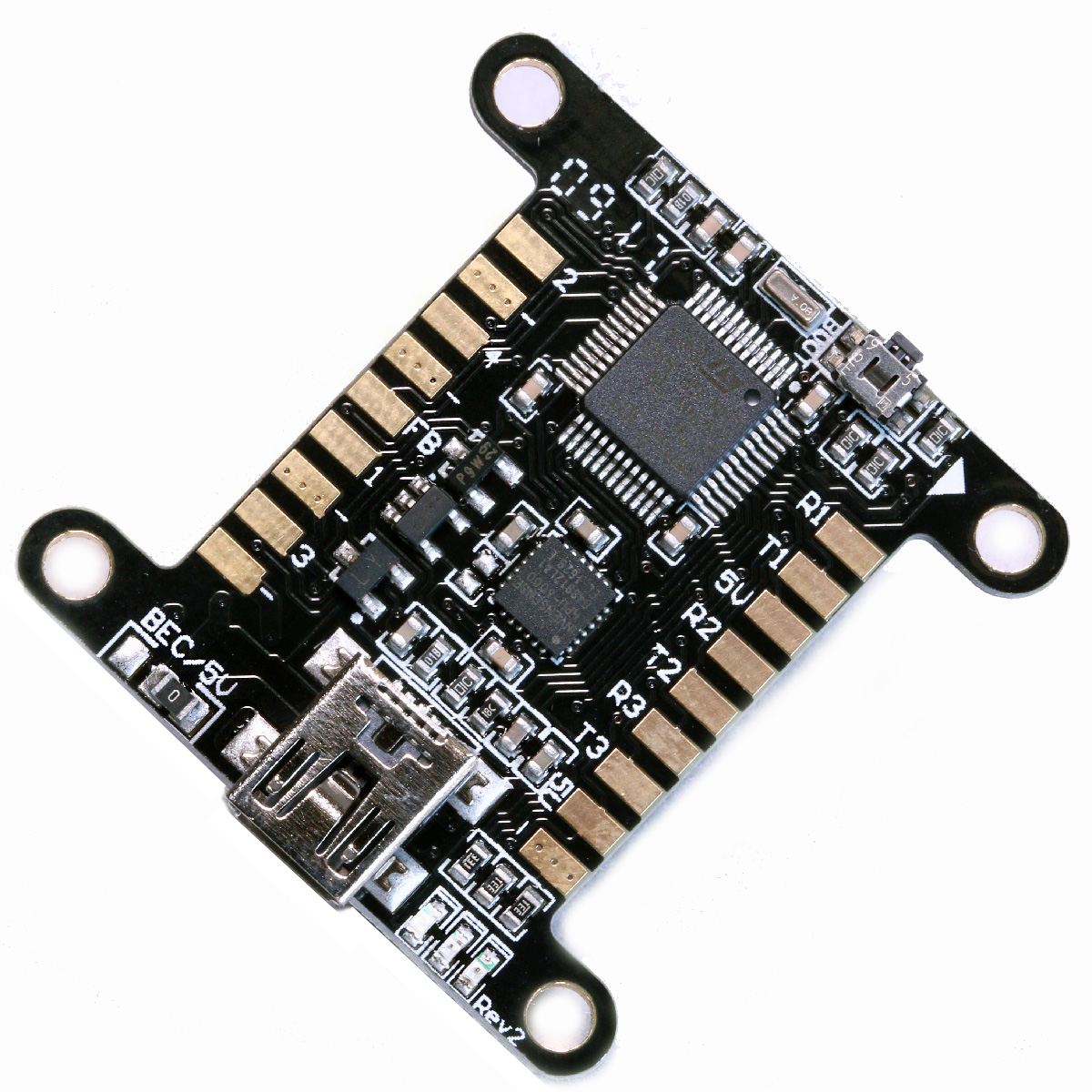


 Made for Bi, Tri and Quad copters.
The F3FC Racing flight controller was designed with 2 things in mind; Performance and cost. To achieve this we chose a 48 pin version STM32F303CC processor and the MPU6000 gyro/accelerometer chip.
The MPU6000 is the least vibration sensitive chip commonly available, which means crisper performance due to lower noise. It is connected through SPI instead of I2C, which allows for up to 8 times higher update rates. This together with the F3 chips capability of running lower loop times vastly improves the flight performance.
Using the 48 pin version of the F303 processor we managed to cut down on cost quite a bit. But you still get 3 UART’s, dedicated USB, 6 PWM’s, I2C, LED port, Current sensor port, Voltage reading and Servo feedback/RSSI. This is achieved by optimising pin connections until we almost went mad, but in the end we did manage it.
The F3FC Racing also has a built in 5V linear voltage regulator. This makes installation easy and clean as no external BEC is needed to power the board or the receiver. However it’s very easy to hook up an external BEC if you would like to power more power hungry things such as a servo, RGB LED’s or a OSD. Just remember to move the little resistor next to the USB connector to “BEC” or you might fry the board! I highly recommend checking out the BabyPDB, which besides being a 36x36mm power distribution board also has built in current sensor and a 3A switching BEC.
The F3FC Racing follows the 36x36mm (30.5mm hole spacing) form factor. It weighs 4.6g. The connection pads are located on the top and bottom edges of the board, just like the popular KISS FC and LUX flight controllers. An easily accessible side mounted boot button is located on the opposite side of the USB connector. This makes entering DFU mode as painless as possible.
This board uses a Mini USB connector instead of the Micro USB commonly used on flight controllers today. This is because the Mini USB is much less likely to break if you accidentally leave the cable in while moving your copter. I know I’m not alone in having destroyed at least one board this way. The F3FC Racing should be able to take a lot more of this kind of abuse.
PPM input is shared with PWM 6. For powering spectrum satellites a 3.3V pad is also available.
The F3FC Racing uses the same architecture as the F3FC tricopter board, which means that it uses the same hex file during flashing.
The F3FC boards are now supported by BetaFlight. Use target “RCExplorerF3” in the firmware flasher tab in the Betaflight configurator.
The F3FC boards are now supported by Cleanflight. Use target “RCExplorerF3” in the firmware flasher tab in the Cleanflight configurator.
Correct signal output for a quadcopters is:
Just like cleanflight/betaflight shows you on the configuration tab.
The correct signal output for a tricopter is:
Pad number 1 = Tail motor
Pad number 2 = Servo
Pad number 3 = Front Right motor
Pad number 4 = Front Left motor
Specifications:
Made for Bi, Tri and Quad copters.
The F3FC Racing flight controller was designed with 2 things in mind; Performance and cost. To achieve this we chose a 48 pin version STM32F303CC processor and the MPU6000 gyro/accelerometer chip.
The MPU6000 is the least vibration sensitive chip commonly available, which means crisper performance due to lower noise. It is connected through SPI instead of I2C, which allows for up to 8 times higher update rates. This together with the F3 chips capability of running lower loop times vastly improves the flight performance.
Using the 48 pin version of the F303 processor we managed to cut down on cost quite a bit. But you still get 3 UART’s, dedicated USB, 6 PWM’s, I2C, LED port, Current sensor port, Voltage reading and Servo feedback/RSSI. This is achieved by optimising pin connections until we almost went mad, but in the end we did manage it.
The F3FC Racing also has a built in 5V linear voltage regulator. This makes installation easy and clean as no external BEC is needed to power the board or the receiver. However it’s very easy to hook up an external BEC if you would like to power more power hungry things such as a servo, RGB LED’s or a OSD. Just remember to move the little resistor next to the USB connector to “BEC” or you might fry the board! I highly recommend checking out the BabyPDB, which besides being a 36x36mm power distribution board also has built in current sensor and a 3A switching BEC.
The F3FC Racing follows the 36x36mm (30.5mm hole spacing) form factor. It weighs 4.6g. The connection pads are located on the top and bottom edges of the board, just like the popular KISS FC and LUX flight controllers. An easily accessible side mounted boot button is located on the opposite side of the USB connector. This makes entering DFU mode as painless as possible.
This board uses a Mini USB connector instead of the Micro USB commonly used on flight controllers today. This is because the Mini USB is much less likely to break if you accidentally leave the cable in while moving your copter. I know I’m not alone in having destroyed at least one board this way. The F3FC Racing should be able to take a lot more of this kind of abuse.
PPM input is shared with PWM 6. For powering spectrum satellites a 3.3V pad is also available.
The F3FC Racing uses the same architecture as the F3FC tricopter board, which means that it uses the same hex file during flashing.
The F3FC boards are now supported by BetaFlight. Use target “RCExplorerF3” in the firmware flasher tab in the Betaflight configurator.
The F3FC boards are now supported by Cleanflight. Use target “RCExplorerF3” in the firmware flasher tab in the Cleanflight configurator.
Correct signal output for a quadcopters is:
Just like cleanflight/betaflight shows you on the configuration tab.
The correct signal output for a tricopter is:
Pad number 1 = Tail motor
Pad number 2 = Servo
Pad number 3 = Front Right motor
Pad number 4 = Front Left motor
Specifications:


 This upgraded version of the tilt mechanism features injection moulded pieces made from black fiberglass reinforced nylon parts. All parts were forged in the fires of Mt. Doom, making it almost indestructible. (It’s the same plastic used by high-end propeller manufacturers.)
This tilt mechanism is designed to be as simple, precise, light (only 10.6g), durable and with as little air resistance as possible. All parts are made from black fibreglass reinforced nylon for maximum durability. The design features a spline directly integrated into part which enables the recommended servo simply slides right in and gets tightened down by the same screw that is used as the pivot point. Simple, strong and easy to assemble.
The tilt is design around 28mm outside diameter motors with a hole spacing of 16 or 19mm, which is a very common motor size. The tilt can handle motors with a maximum motor size of about 33mm outside diameter. You can squeeze a 35mm motor but it’s not recommended, the bell might rub against the servo. DT750 type motors work well as they stick up high enough not to interfere with the servo.
Designed for 10mm booms the tilt simply attaches using zip-ties that are design to work as “mechanical fuses”, breaking and absorbing energy in a crash, protecting the important parts. It also makes it much easier to repair at the field, just bring some zip-ties.
The tilt is designed around the BMS-210DMH / TGY-210MH servo, which is a really strong and tough servo with great precision. It uses magnetic induction instead of a potentiometer. This means that in a crash, when the servo is subjected to way to much force the magnetic encoder looses track of where the output shaft is and it stops trying to make the servo fight the force, saving the gears. This servo also has a large spline diameter of 6mm which makes it possible to you to 3D print the spline directly into the tilt if you wish to make one yourself. This makes it super strong and slop free. It also uses a M3 servo horn screw, which I took advantage of by designing the tilt to use a 40mm long M3 screw as the pivot axis. This screw simply screws straight through the whole tilt and straight into the servo. The design also works with a other servos directly (list below) or you can use almost any servo as long as it has a maximum distance of 8mm from the bottom of the servo body to the bottom of the spline.
Specifications:
This upgraded version of the tilt mechanism features injection moulded pieces made from black fiberglass reinforced nylon parts. All parts were forged in the fires of Mt. Doom, making it almost indestructible. (It’s the same plastic used by high-end propeller manufacturers.)
This tilt mechanism is designed to be as simple, precise, light (only 10.6g), durable and with as little air resistance as possible. All parts are made from black fibreglass reinforced nylon for maximum durability. The design features a spline directly integrated into part which enables the recommended servo simply slides right in and gets tightened down by the same screw that is used as the pivot point. Simple, strong and easy to assemble.
The tilt is design around 28mm outside diameter motors with a hole spacing of 16 or 19mm, which is a very common motor size. The tilt can handle motors with a maximum motor size of about 33mm outside diameter. You can squeeze a 35mm motor but it’s not recommended, the bell might rub against the servo. DT750 type motors work well as they stick up high enough not to interfere with the servo.
Designed for 10mm booms the tilt simply attaches using zip-ties that are design to work as “mechanical fuses”, breaking and absorbing energy in a crash, protecting the important parts. It also makes it much easier to repair at the field, just bring some zip-ties.
The tilt is designed around the BMS-210DMH / TGY-210MH servo, which is a really strong and tough servo with great precision. It uses magnetic induction instead of a potentiometer. This means that in a crash, when the servo is subjected to way to much force the magnetic encoder looses track of where the output shaft is and it stops trying to make the servo fight the force, saving the gears. This servo also has a large spline diameter of 6mm which makes it possible to you to 3D print the spline directly into the tilt if you wish to make one yourself. This makes it super strong and slop free. It also uses a M3 servo horn screw, which I took advantage of by designing the tilt to use a 40mm long M3 screw as the pivot axis. This screw simply screws straight through the whole tilt and straight into the servo. The design also works with a other servos directly (list below) or you can use almost any servo as long as it has a maximum distance of 8mm from the bottom of the servo body to the bottom of the spline.
Specifications:
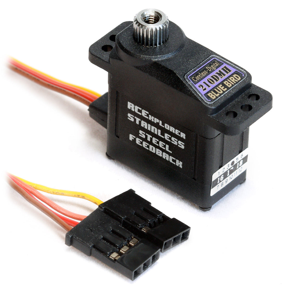


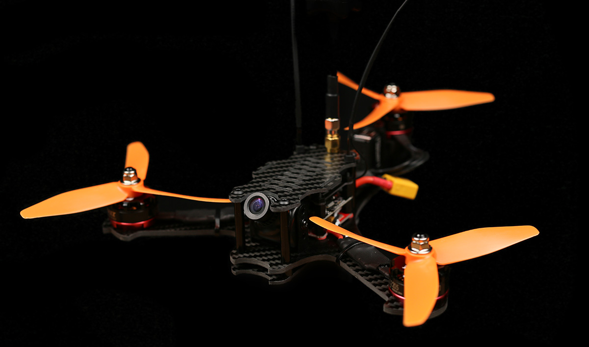


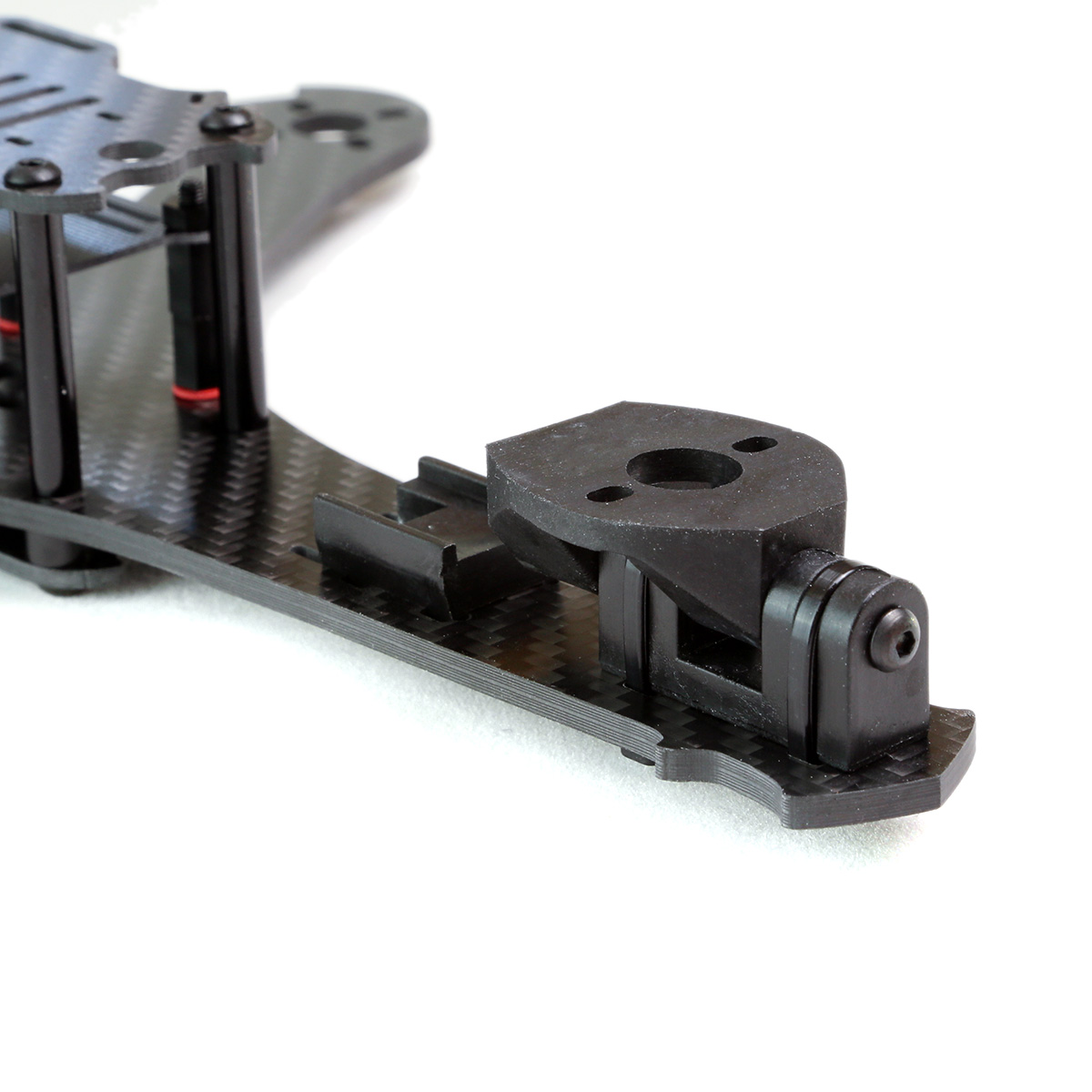


 The RCExplorer Bicopter is designed to look as badass as possible, and I think we succeeded. The frame is entirely made from high-quality 3k twill weave matte finish carbon fiber. This makes the RCExplorer Bicopter frame lightweight, durable and worth drooling over.