I just finished up a guide on how to make your own GoPro3 video out cable for FPV. I hope you guys will enjoy it!


I just finished up a guide on how to make your own GoPro3 video out cable for FPV. I hope you guys will enjoy it!


GoPro just released their new Hero3 HD camera lineup, which boasts being 30% smaller, 25% lighter while being able to deliver 1080p in 60 frames per second and even 2.7K in 30FPS .
But while shrinking the camera, Gopro removed the 2.5mm video out jack. But fear not, the GoPro 3 is still able to output the composite video we need for FPV flying. Instead of a normal 5 pin mini USB connector, GoPro chose the much less common 10 pin version. This connector now contains the standard USB pins as well as microphone input and the video output.
Unfortunately it’s not as straight forward as simply soldering the cable to the connector. A 100K ohm resistor is also needed to kick the camera into video out mode. In this guide I’ll guide you through making your own cable, so that you too can enjoy the live output of this great camera, without having to dish out 20$ for a bulky cable from GoPro.

First off you need to get your hands on a 10 pin mini USB connector. They can be found on various electronic stores online. I ordered mine here. You also need a 100K resistor. Any watt rating will do, as there will only be microamps going through it. I used a standard thru-hole 1/4W resistor I had laying around. It’s a little big so if you need to order the resistor I recommend getting a smaller one, like a 1/8W. You also need a cable of some sort. I used a 32 AWG servo lead, which is nice and thin.

This is how we’re going to connect everything.

I removed the unused pins to gain more space, reduce the chance of a short and make it easier to work on.

I soldered the cables first, which I think is a good move as they are the most fiddly. Do not use to much heat on the soldering iron or the connector and/or the insulation on the wires will melt.

The resistor is connected between pin 7 (the ID pin) and ground. This is how I mounted my resistor. The metal case of the connector is connected to ground inside of the GoPro, but if you wanted you could connect it to the video ground pin instead. Connecting it to the case does make it very sturdy though and there is no chance of it shifting around.

Pretty compact considering the size of the resistor.

I wanted my connector to stick out as little as possible, so I bent the wires 90° back over the resistor.

Yay! It works! Time to make the cable robust.

To make the cable as though as possible I decided to use “InstaMorph”, which is a plastic that after it’s been heated up can be shaped and molded into almost any shape. Once cooled of it becomes incredible hard and very though. Check out Chads excellent video showing how to use “InstaMorph”

Instamorph is awesome.

Pretty streamlined but still easy to grab and pull out.

Time to paint it.

The paint stick well to the Instamorph.
Done! Works like a charm, low weight, robust and easy to plug in and out. What more could ask for?

Here is the DIY cable vs the original GoPro cable.

Much more streamlined.
Now get out there and make awesome FPV videos using your new GoPro3 video out cable!
I’ve been flying FPV for a couple of years now and I’ve build many ground stations. However these ground stations have always been cumbersome, fragile and/or not very pretty. Now I’ve finally tried enough configurations of antennas, receivers, diversity, tracking and so on to know what I want and need for my type of FPV flying.
In this first part of my Overkill FPV ground station build I show how I built the Helical antenna.

Click here to get to the build log
More to come!
I’ve been flying FPV for a couple of years now and I’ve build many ground stations. However these ground stations have always been cumbersome, fragile and/or not very pretty. Now I’ve finally tried enough configurations of antennas, receivers, diversity, tracking and so on to know what I want and need for my type of FPV flying.
The antenna I come back to time after time is the Helical. It’s perfectly circular polarized, extremely wide band, has a good beam width and looks cool. Its always worked flawlessly for me so that’s the antenna I’ll be using for my overkill ground station.
One thing I’ve come not to underestimate is the ease of transport. If a ground station is too cumbersome, fragile or has things that gets cough everywhere, you’re are much more likely not to bring your FPV gear on a trip, or whip it out quickly if you see something interesting. Thereby missing great opportunities to fly and catch good video. Therefore this ground station will be compact, robust, light weight and easy to carry. If I can carry my tricopter, transmitter, and ground station with ease to the car in one trip I’ll be satisfied.
The last thing I want this ground station to be is professional looking. I do not want to feel ashamed when I set up my gear at a video production set. With all that in mind, let me present my overkill FPV ground station. I’ll start of with the antenna itself. (To build you own helical antenna I can recommend reading this guide)

This is going to be the reflector plate for the antenna. It’s a stove burner cover made out of stainless steel which I found it in a cupboard at home (don’t tell my wife). In sweden the largest burner on a stove is 21cm in diameter and this cover happens to be 23.2 cm across at the narrowest point, which is exactly the size of a 1280Mhz reflector.

I used a dremel with cutting discs to remove the lip of the cover. The stainless steel is very tough and I used up 17 or so discs to get it of.

I drilled a hole for the active part of the antenna wire at the point where the coil will begin on the other side.

Pre tinning the stainless steel is a good idea as it takes a lot of heat and you don’t want to overheat the coax cable.

Soldered in place.

Back side. Notice that I’ve sanded the plate (I’ll be painting it later and want the paint to stick properly)

Front side. The active part of the coax poking through.

I decided to paint it orange. I’m very partial to orange and I think it will look great with the black parts.

Time to make the antenna coil. To do that we need copper. I had this cable laying around that will be perfect.

1mm thick solid core copper wire.

The spray can happened to have the right diameter for forming the coil. The object you wrap around should ideally be 15% or so smaller than the diameter your trying to achieve as the wire springs back out a bit after forming. The tape on the can is so that I get the correct coil spacing.

Coil all done. This antenna is going to be lefthand polarized hence the direction of the winding.

In order to make this antenna as though as possible I decided to make the the coil support extend over the edge of the edge of the reflector plate. Cut from 1.5mm G10 fiberglass on my CNC machine

This really made the antenna very strong and robust.

Back side of the antenna.

The glassfiber support was glued to the reflector plate using super thin CA.

The coil in place. Simply wound it through the holes.
The coil is well protected.

Top view.

Helical antennas usually have an impedance of 100-140 ohm. Our FPV gear needs a match of 50 ohm. To achieve that you add a matching transformer. I used the IBCrazy’s tapered match on my antenna.

I used a SWR meter to achieve the best match possible. I added a lot of hot glue to toughen up the weak spot where the antenna cable and coil meet.

The antenna done! I must say it looks splendid.

The side panels and bottom that will make the body of the ground station fresh from the CNC.

Test fitting.

I used small 10×10 wooden pieces glued to the sides and then screwed from the bottom to assemble the body. This will make it easy to take apart if necessary.

Removed the protective plastic. The text and lines have been milled down about 0.3mm and the plan is to inlay it with paint.

I used spray paint as it has close to zero surface tension and thus flows into the cracks very willingly.

Done! Looks way better than expected.

To be able to easily turn the ground station on and off, I decided to mount switches on the outside of the case.

I found these awesome safety switches on biltema (A swedish hardware/automotive store). Apart from looking cool they also prevent accidental on or off turning of the ground station. The reason why I chose to go with two separate switches was that these safety switches automatically switches back off when you flip down the lid again. Since that would make it even more prone to it being turned of by accident, I went with two separate switches and a relay with “self holding” circuit. More on that later…

This is the receiver I used. It’s a 12 channel 910-1360MHZ receiver from ReadyMadeRC.com with a upgraded saw filter

I like always knowing how much battery I have in all my gear. That is why I use the Aurora 9 with telemetry on all my aircraft. My ground station is no exception. So I decided to integrate a LiPo capacity checker.


The LiPo checker is automatically powered on with the rest of the ground station.

To have the two power switches work the way I wanted I needed to add a relay. I’ll try to explain in words how I connected everything. The OFF button is configured as normally closed. The ON button is configured as normally open. The positive wire from the battery is connected to the OFF button which is connected in series to the ON button. The ON button is connected in series to the coil of the relay. The other side of the coil is connected to the ground. So when the ON button is pushed the relay coil becomes energized and it switches it’s output. The center pin of the output on the relay is connected to the possessive wire after the OFF button. The normally closed output of the relay is connected to the all the ground station gear, but also back to the positive part of the coil on the relay it self. Which means that when you flip the ON switch the relay switches its output and then supplies it’s own coil, bypassing the ON switch. This is called a “self-hold”. As soon is the relay is turned on it stays on until the power is cut. This is done by the OFF switch which is normally closed, which means that it’s going to break the circuit when it is flipped. This simple circuit enables the ground station to be powered on without either switches being turned “on”, which means that the lids can be closed during operation.

Added some hot glue to protect the gear.

Since I quite frequently give “rides” to other people, I needed a second video output. This tiny video splitter from Flytron was perfect for this application. It works with 12V and it’s small. No nonsense, it just works the way it’s supposed to.

Here is the two video outputs. I decided to go with one servo connector for my custom video goggles and a standard RCA connector for the secondary output.

The servo connector also supplies my video googles with 12V, which is great as I don’t have to have a yet another battery to worry about.

Ready for action.

Built in angle of around 40°

Inside.

Goggles hooked up.

The cable is protected nicely.

Secondary goggles plugged in.

Powered up.

Video goggles fits snuggly with no chance of falling out.


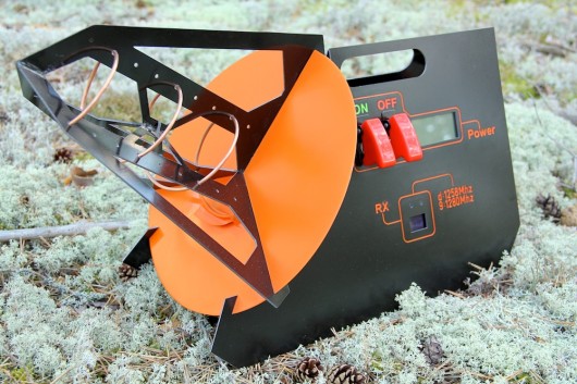
In the wild.


The ground station feels stiff yet light.

The display is very clear and easy to read.

Easy to change channels, but hard to do it accidentally. I only added to two frequencies I use.

Time to fly.
So far the new ground station has been a success. It’s worked flawlessly. It’s easy to transport. It looks good. It’s robust. The antenna is awesome. It’s also possible to take it apart for easier transport in suitcases, which was very nice for my US trip. I’m very glad I took the time to built it and I think I’ll use it for a very long time.
So what is your thoughts about it? What would you have done differently? Leave a comment and let me know!
Have been working on this project since March this year – finally it flies! The breakthrough for me was getting some HK KKV2.0 boards. Got my new flamewheel style 450 quad and the tricopter flying on the same weekend. Haven’t had much luck with the old KK boards, but I have a few so will eventually try to get to grips with them.
I just wanted to share something relating to the 1.5 Tricopter, but it may be useful for other versions. I’ve had the unfortunate problem of the forward arms swinging back on the craft under accelleration and destabilising the copter causing a crash. I’ve installed a lightweight pin retainer system using 1.5mm piano wire and zip ties that will prevent this happening in future, but still allow the arms to fold in event of a crash (though that bit is untested as yet!).
notes:
– When bending the wire don’t do a full 90 degree bend – this allows the wire to spring-lock against the hole and retaining zip tie.
– Two small holes are drilled – one through the frame plates and spar to lock the arms in position and one just through the spar clear of the frame for securing the locking wires when the tricopter is folded. Hopefully the photos should make it clear.
– You don’t need to cinch down the yellow zip tie – it remains loose for reuse as the spring of the locking pin pushes against it.

Locking pins to the side of the copter showing the degree of bend and also the location of the two holes in the arms.Continue Reading
After about 24 hours of traveling I finally arrived at my second home, also known as Chads basement. It was about a year ago that I last smelled the lovely smell of american hot-glue down here. Not much has changed, if you discount the alarming infestation of planes, which has grown considerably.

Luckily I’m here now to help crash a few planes and help battle this ever growing population of planes. Stay tuned!
http://www.youtube.com/watch?v=MabNK5PUfEA
WHERE: Jurere Beach, Florianópolis, Brazil
TRICOPTER ESPECIFICATION:Continue Reading
After helping David film fireworks in Blackpool i just had to do my own version!
http://vimeo.com/52961424
🙂
After a very long and much more difficult process than I ever imagined, I finally got my J1-visa!

Last thursday I had the final interview at the American embassy in Stockholm. After standing in line outside in +4° weather for about 1 hour and 40 minutes I was finally let in through the security check. Well inside the process didn’t take more than 15 minutes. I had all the paperwork ready and was well prepared. The three people that were in front of me in the line weren’t though and had to run on to the bank or post office. After the leaving my fingerprints and answering a very nice ladies questions I was allowed to leave. – “Your passport with the visa will arrive within a week”. And yesterday it did!
I have now booked a flight that leaves at 9am Sunday morning from Stockholm Arlanda. FliteTest, Chad and the American continent, I hope you are ready for 18 months of Swedish awesomeness, because here I come!