
 Ever wondered how to get live video from a GoPro Hero HD camera? I know lots of you do, because I’ve got a ton of e-mails asking about it. That’s why I decided to make a guide explaining in detail how to get your GoPro Hero HD camera into Live output mode. It doesn’t require any modification what so ever to the camera. It’s also safe, easy and fast to do.

Click here to read the guide
New guide: GoPro Live output
Leave a comment
Promotional video
The guys over in France have made a promotional video for Domaine du Planet using some of the material I shot during my stay.
I have not edit it, or have any part of making it (except shooting the aerial video). I’m glad that they could use some of the videos from the Tricopter.
New video
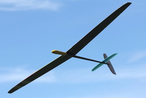
In this video I “show and tell” about my new F3K/DLG machine. Subtitles are available for those of you that doesn’t understand Swedish, click on the CC button and enjoy the show.
Domaine du Planet review

Welcome to France and welcome to Domaine du Planet.
In a valley, 40 km from Marseille, you will find a hidden paradise known as Domaine du Planet. At this hotel they specialize in RC aircrafts and they have a local RC-club here. You can come here to enjoy your holidays and fly your models (or rent one) in a beautiful setting, and if you need to acquire some flying skills, you can attend a training course or book individual lessons with a trainer. When you aren’t flying (or if you bring family members that don’t share your interest) you can cool down by the pool, play tennis or other ballgames, go for a hike or fish in the small lake.
Continue Reading
The F3K/DLG A2 build
F3K is “a multitasking contest where RC gliders must be hand-launched and accomplish specific tasks.” Which means that these airplanes must be super light weight to be able to “absorb” the lift of rising air and really stiff to cope with the violent launches. These models are commonly known as DLG’s, which is short for “discus launch glider”, due to their unique launching style. One wingtip is equipped with a “launch peg” which is gripped with two fingers. To launch the airplane you spin one revolution around your own axis and throw the DLG, just like a discus (hence the name). A skilled pilot can launch a DLG to an altitude of 70 meters and then stay up indefinitely if there is enough thermal. This airframe I’m about to build is called the “A2” and is made by two very skilled F3K pilots that that just happens to be friends of mine.

The kit. An oval carbon fuse and glassed wing.

2.4Ghz compatible kevlar pod.

Drilled holes for the nuts that’s going to hold the wing on.

Made a slot for the ballast compartment.

3mm plywood to get some surface for the nuts.

Glued the nuts in place as well as the ballast chamber.

Drilled holes in the wing. This was a bit tricky to get perfectly straight and true but if you’re careful and take your time it shouldn’t be any trouble.

Cut a slot in the boom for the tail fin.
Glued the tail fin on using CA. Be very careful to get it mounted straight.

Mounted the control horn for the elevator. Be sure to use foam safe CA.

Hmm the boom needs a slot for the control horn.

Much better.

Tailplane glued on. Make sure it’s straight to the wing.

Time to cut the ailerons. I used a exacto knife. I was extremely careful only to cut trough the top layer of glassing.

I then used a hacksaw to cut all the way through on both sides of the wing root and the tips of the ailerons.

Beveled the the hinge using sandpaper.

The tip of the ailerons doesn’t extend all the way to the wingtip. This is to get rid of unwanted vortexes created by the sharp edges ailerons usually have.

I used a dremel to machine out the servo bays.

Easy as pie.

Added carbon fiber control horns.

Servos test fitted.

Servos glued in place and covered using clear packing tape.

Servo cables comes out on the bottom of the wing.

Made a hole in the fuselage for the cables.

Time to mount the elevator servo. I first glued it to the balsa piece supplied in the kit.

Glued into the fuselage.

Linkage done and hooked up. It’s made from a super light weight string not unlike dental floss and it’s the strongest sting I’ve ever come across.

One Hitec optima 7 that needs to loose some weight.

Casing removed.

Since I’m going to use 2S LiPo to power my DLG, I needed a voltage regulator. I choose to build my own using a L4940V5 low voltage dropout regulator and a couple of capacitors. This regulator is rated at 1.5A continuous with a drop out of 450mV.

To be able to use as short cables as possible, I mounted the regulator on the side of the receiver. I’m powering the receiver through the “SPC” port which means that I get the voltage of the LiPo sent back to the transmitter. That way I always know exactly how much power I have left in the onboard battery.

Receiver done. I also exchanged the heavy boda antenna for a light weight whip.

Time for the lipo to get a work over. Original weight: 32 grams

New weight: 28 grams. Removed the long and heavy power cable, unnecessary padding and tape.

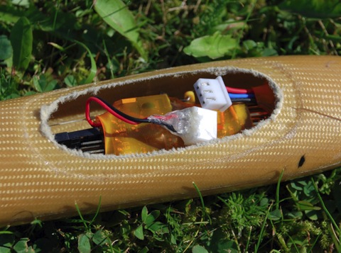
Jammed into the nose.

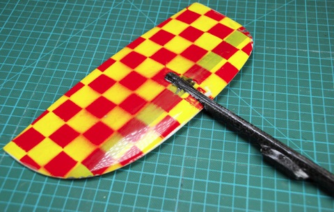
Throwing peg mounted and the edge of the wing rounded to prevent cutting my fingers open.

Canopy “latch” system – a 1 mm carbon rod glued in the middle.

Simply slide one end of the carbon fiber rod underneath the edge of the fuselage and slide it back until the front end of the rod can be pushed under the front edge of the fuselage. Then slide the canopy in place.
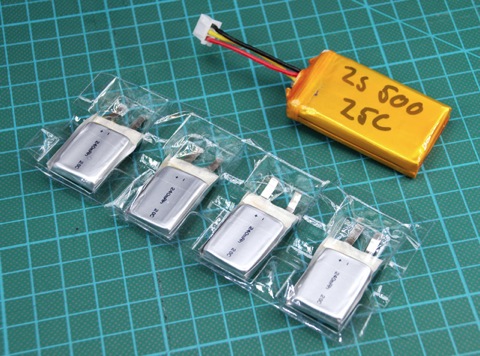
I wasn’t quite happy with the first battery as I couldn’t get it far into the nose to get the CG right. So I decided to make another one out of loose cells.

I paralleled the cells two and two and then took those cells and put them in series, making a 2S2P 480mAh battery.

Size of the first battery: 54*31*10mm
Size of the second battery: 28*21*20mm
Weight: 22 grams.

Done!

I had to exchange the tail fin I originally mounted for a lighter one in order to get the CG a bit forward.


I also moved the tail servo forward a bit. Since the new battery is smaller I can still get it out without any trouble.
Despite all this I had to add a couple of grams of lead to the nose to get it properly balanced.

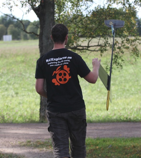
Time to fly!

Up into the sky!
Here is a short demonstration video:
Update:
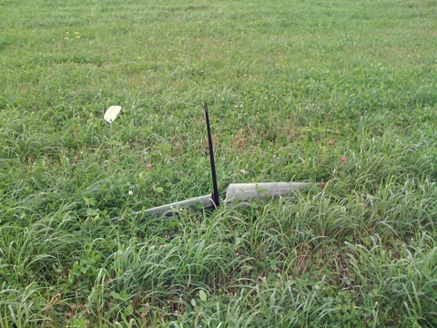
The elevator came loose just as I was throwing. Ooopppss.
Update 2:

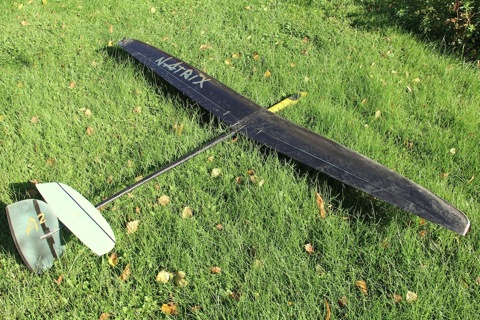
I bought a new carbon fiber wing from a friend that crashed his DLG and broke his fuselage.
Time to fly.

Flies like a dream.
This is still my favorite line of site plane of all time.
Here is another video filmed just for fun:
Santa must have confused the date
When I arrived home from Italy 7 new packages had arrived. I didn’t quite expect that many packages to arrive during my absence, but I’m not complaining.

The packages contained:
1 Twinstar II model
2 Flymentor 3D
1 FY20A Flight stabilization system from FPV-flying.com
2 Simple OSD XL
1 GPS
9 Counter rotating 12*3.8” Slow fly APC props
9 12*3.8” Slow fly APC props
6 Hobby King 401B AVCS Digital Head Lock Gyro
2 300mW 1.3GHz video transmitters
1 DVD ”Hand Lauch pro clinic” from Radio Carbon Art
1 Fatshark video goggles
1 Aiptek Z500+ HD camera
Now all I need to do is to find time to play with all my new toys
180° Servo modification
First of all why would you want to do this? My answer is:
– Panning of a FPV camera.
It’s so nice to be able to look 90° to either side and be able to see the wings. It makes the FPV experience feel even better. So how do you get 180° of rotation from a servo? There are 3 ways to do this;
1. Buy a “servo stretcher”
It’s a little device that is plugged in in-between the servo and receiver and “broadens” the PWM signal. This doesn’t require any modification to the servo but you need to watch out, not all servos can be used.
2. Buy a digital servo that is programmable
This can be quite expensive as the prize of the servo is higher and you need to buy the programing interface. But once you have these you have a nice digital servo that you can program to make 180° of travel without any modifications.
3. Modifying a servo with resistors
This is the method that I will show you here. It’s cheap and nearly any servo can be used. But you need some basic electronics understanding and be able to solder.
The servo I use in this guide is a Turnigy 1160A mini servo
We start of by disassembling the servo.

You need a small philips screwdriver.

This is the top piece of the servo. I want to get the absolute most travel I can get out of the servo, so I will remove the mechanical stop.

I used a dremel to remove the plastic limiter.

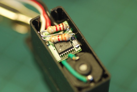
This is the circuit board that we will be modifying.

This is the way to hook up the resistors. In parallel with the pot.
Update: Some servos work better with the resistors in series with the pot.

Both parallel and series works but some servos works better with the resistors in series, other with the resistors in parallel. If the servo doesn’t work like “normal” except for 180° of movement after the modification, I recommend switching the configuration of the resistors.

Normally I would just solder two 2.2K ohms resistors in parallel with the pot.

But this cheap servo does not have its center in the middle of the pot, which results in 180° of travel in on direction whilst in the other direction it exceeds the pots max value, which results in the servo doing a 360° rotation. To fix this I hooked the servo PCB to my trusty experiment board and paralleled the pot with a couple of 20 turn 5k trim-pots to determine what values I needed.

I ended up with one 3.3K and one 1.2K. This resulted in nearly 180° of travel in both directions and perfect centering.


Original travel (with 100% EPA) <—–> Modified travel (with 100% EPA)

With a 180° servo it’s possible to get this view.
If you try it out be sure to leave a comment!
I’m home again!
Wow what a trip! My feet have never been so tired as they were after two whole days of walking in Venice. But it was worth it. Venice is a beautiful town. The best thing that happened in Venice was that I got to take a helicopter flight above the town in the front seat of a Robinson R44.


After Venice we went to an island called Ustica. It’s a pretty small volcano island outside of Sicily. The snorkeling there was awesome. It was like swimming in an aquarium. I brought the GoPro camera with it’s waterproof case and made a short video for you guys:
Wonder were we’ll travel next time, any ideas?