
I just updated the Tricopter V2 build log. Now you can build your own KK controller.

Click here to get to the build log
Tricopter V2 Update
Leave a comment
Looking for a new job
It’s time for me to switch jobs. I currently work in the electronics manufacturing business (who would have guessed?). Problem is that I’m one of the last one in and thus will be one of the first ones out, if the company starts laying off people, which it seems like they will around Christmas.
So I thought I might ask you guys; Anyone know of a good place to work that is currently hiring? Preferably in Sweden.
Or what kind of job do you think I should be searching for?
I need all the help I can get.
The Tricopter V2
I’ve just uploaded the first part of the Tricopter V2 build log. The Tricopter V2 was actually started it’s life nearly 6 months ago and during that time I’ve been perfecting it. After many changes, crashes and modifications I’m now very happy with the way it flies. I know many of you have been waiting for this for a long time. I hope you will like it.

Take me to the build log!
The Tricopter V2
This build is an evolution from the Tricopter V1 and V1.5
Click here to read the build log.
Be sure to check out the Tricopter V2.5 build as well!
This tricopter uses the open source KapteinKUK flight controller. Read more about it here.

The V1.5 disassembled. I will be using the V1 upper plate again.

This is my first KapteinKUK controller board. It’s not very pretty but it works like a charm. (I’ve since made my own layout more suited for DIY etching and assembling, more on that later on)
The KapteinKUK board isn’t complicated at all. It comprises of 11 capacitors(Some taken from the HK401 gyros), 9 resistors, 3 potentiometers (taken from the HK401 gyros), 3 gyro sensors (taken from the HK401 gyros), 1 LED, 1 voltage regulator and 1 Atmega CPU.
So why build a KK controller when you can use 4 standard gyros?
- The KK board only uses 3 gyro sensors (instead of 4) and does the mixing on the board. Which means that you can use nearly any transmitter.
- It’s also a lot more stable. A standard gyro sends an update to the ESC’s 50 times a second, the KK board 180 times a second. It feels solid and like it’s flying on “rails”.
- It’s safer. You have to arm the board by moving the throttle stick to the bottom right. This effectively prevents any accidental takeoffs.
- No more need to “jump start” the gyros, which was necessary with the HK401B gyros.
- It’s smaller and lighter than a 4 gyro setup.
- Only requires 4 channels.
- It can be reprogrammed to control either a tricopter, quadcopter, hexacopter or a hex-Y-copter, without any hardware modification.

Here is a size comparison of the KK board to a HK401B gyro.
On with the build.

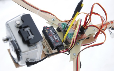
The KK board mounted on the tricopter.

I made a dampened GoPro camera mount. The dampeners are made from a kind of rubber I got from work.

The battery is mounted on the underside of the camera mount to reduce the vibrations even more.

Everything in place.

Time for the first flight.
First flight impression: Wow!
The difference in stability was much more than I had anticipated. It feels more crisp, precise, locked in and stable. But I ran into some trouble on the first flight. One of the Hobbyking SS18 ESC’s kept shutting down after 15-20 seconds of flight. After some testing I found that the SS ESC’s do not like the 180Hz update rate of the KK board. The SS ESC’s are programmed to shut down if they receive a incorrect PPM signal. The software recognized the high update rate as a faulty signal and started to shut down. This is a great feature when you’re flying a plane with a FM receiver, but not when you’re trying to fly a tricopter. Unlike sensible people I did not buy three new ESC’s capable of running the higher PPM frequencies, but rather decided to try and modify the SS ESC’s.

To my surprise there was already a whole thread on rcgroups on the subject. Some very clever people had already written custom “I2C” and “high speed PPM” codes for this kind of speed-controllers and all I had to do was solder a couple of wires and flash the Atmega processor with the new code using a AVR programmer.
(I strongly recommend getting TURNIGY Plush Speed Controllers instead. They work perfectly out of the box without any modifications)
After the ESC modification the tricopter flew perfect the entire battery. I did notice that the dampened GoPro mount that I had originally build from glass-fiber was way to flexible with the camera mounted. So I replaced the glass-fiber with 3mm plywood which worked beautifully.

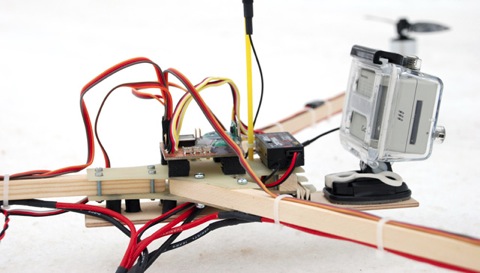
FPV setup comprising of GoPro, Flytron SimpleOSD XL and 300mW 1.3GHz video transmitter mounted.

These two videos were taken with this precise setup during my stay on the RC hotel Domaine du Planet in France:
A new KK board is born
Since I was so satisfied with the KK controller board I decided to design my own layout that was better suited for DIY etching and assembling. I make all my designs in the CadSoft Eagle layout editor.


This is the design I came up with. I have made around 20 or so boards now and I’m perfectly satisfied with the layout. To make life easy for you, I made a complete package of the layout with component placement charts and part list.Click here to download it.
To etch your own board simply follow this guide.
These are the components you will need:
IC1: Atmega48/88/168/328 (TQFP)
IC3: LM317LZ (TO-92 or TO-220)
R1: 100 Ohm (0805)
R2: 100 Ohm (0805)
R3: 100 Ohm (0805)
R4: 4.7 Ohm (0805)
R5: 10 – 25K Ohm trim potmeter (3314j) (From the HK401B gyro)
R6: 10 – 25K Ohm trim potmeter (3314j) (From the HK401B gyro)
R7: 680 Ohm (0805)
R8: 10 – 25K Ohm trim potmeter (3314j) (From the HK401B gyro)
R9: 220 Ohm (0805)
R10: 68 Ohm (0805)
R11: 4.7 KOhm (0805)
R12: 100 Ohm (0805)
C1: 22 – 47uF (EIA 3528-21 / Kemet B) (From the HK401B gyro)
C2: 22 – 47uF (EIA 3528-21 / Kemet B) (From the HK401B gyro)
C3: 22 – 47uF (EIA 3528-21 / Kemet B) (From the HK401B gyro)
C4: 22 – 47uF (EIA 3528-21 / Kemet B) (From the HK401B gyro)
C5: 0.68uF (EIA 3528-21 / Kemet B)
C6: 0.68uF (EIA 3528-21 / Kemet B)
C7: 22 – 47uF (EIA 3528-21 / Kemet B) (From the HK401B gyro)
C8: 0.68uF (EIA 3528-21 / Kemet B)
C9: 22 – 47uF (EIA 3528-21 / Kemet B) (From the HK401B gyro)
C10: 2.2uF (EIA 3528-21 / Kemet B)
C11: 22 – 47uF (EIA 3528-21 / Kemet B) (From the HK401B gyro)
LED1: (0805) (From the HK401B gyro)
4 Male servo leads for connecting to RX (From the HK401B gyro)
6 3-pin pinheaders for connecting to the ESC’s
Drill sizes:
0.7mm via holes
1-1.1mm on the rest

Here is my board which I have drilled and soldered the via’s.

Next I recommend soldering the Atmega processor in place. (Note that marking of pin1, this marking is not to be drilled out, it is not a via) As you can see in the picture I’ve already soldered a couple of other components, but I recommend starting out with the processor.

Processor in place as well as most of the resistors and capacitors.


The top side nearly complete.

Many of the components needed can be taken from the HK401B gyros.

Simply desolder the pots, capacitors, leds and the gyro sub board from the gyros.

I recommend covering the gyro sub boards in hot glue for protection.

Done! I’ve put on a layer of electronics clear coat to protect the board from humidity and corrosion.
Now it’s time to load the software into the Atmel CPU. In order to do that you need a AVR programmer. If you don’t have one I can recommend this one.
I used AVR studio, but you can use nearly any AVR software.
First program these fuse settings:
SELFPRGEN: unchecked
RSTDISBL: unchecked
DWEN: unchecked
SPIEN: checked
WDTON: unchecked
EESAVE: unchecked
BODLEVEL: 1.8V
CKDIV8 : unchecked
CKOUT: unchecked
SUT_CKSEL: Int RC osc. 8MHz
To make sure that the CPU is working properly and that the fuses are correct, load this software into the CPU first.
It’s a simple clock test. All it does is toggle the led on and off every minute. Measure the time between these toggles. It should be exactly 60 seconds (+-3 seconds).
Now it’s time to do load the final firmware. Download the latest firmware for the multicopter you wish to control here. Flash the CPU and you’re done!
Follow these instructions before attempting the first flight.
The final Tricopter is born
After a lot of experimenting with different props and arm lengths I finally found the winning combination for my style of flying.
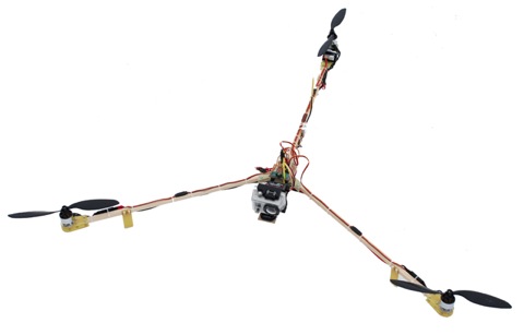
Smaller props and longer arms was the way to go.

The Tricopter V2 has 50cm arms instead of 40cm and uses 9*4.7 props instead of 10*4.7. Smaller props are lighter and have less wind resistance which means that they can change their speed quicker, resulting in grater stability. Always use as small props as you can. It should hover around mid-stick. If it’s under that you can probably use a smaller prop.
Longer arms also improves stability as the props are moved further from the center of gravity. This means that the props much travel a further distance to bank the arm to the same degree.

I love the simplicity of the KK-board setup.

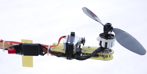
The tilt rotor mechanism I built nearly a year ago still works great and have never broken. Some of you might have noticed the zip-tie around the motor. That is to balance the motor-bell.
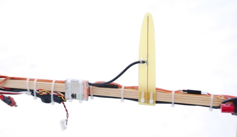
Video TX equipped with a dipole antenna.
Specifications:
Motors: 2213N 800Kv Brushless motors
ESC’s: TURNIGY Plush 18amp Speed Controllers
Battery: 3s Turnigy 25-35C 2200mAh LiPo
Servo: BMS-385DMAX Digital Servo (Metal Gear)
Props: GWS 9*4.7 (For AUW <1kg), GWS 10*4.7 (AUW >1kg)
Arm length: 50cm (center to motoraxel)
All up weight: 1001 grams (Including battery and camera)
Because you asked for it, here is the PDF template of the center plates:

Click on the picture or here to download
Be sure to set the page scaling to 100% when printing.
Due to popular demand I now offer pre-cut V1 tricopter frames!
Now get building those Tricopters! Be sure to post your pictures.
Here is a video from the final Tricopter V2:
I won!
Every month FPV-Community has a FPV video competition. I’ve participated in nearly every one, but have always come second to Trappy. This month however, Trappy didn’t participate and I won for the first time! First price was a $50 coupon HobbyWireless so I ordered a new GoPro camera.

This is the video I entered in the competition:
I’m mentioned
Yay I’m mentioned on a Flitetests review on the F-18. I tipped them off on using a brushed ESC to control the brightness of LED’s and they took the idea and took it a step further:
Keep up the good work guys!
New video: “Leaf blower”
Fall has come to Sweden and I couldn’t resist blowing some leafs around.
I wonder what the guy in the tractor thought when he spotted the tricopter
The octo flies!
I figured out how the software worked (after a bit of trial and error) and finally got it configured with the proper config file, balanced the props and hooked up a battery and took it out for a spin.

Read more on the build page
MK Octocopter almost done
The Mikrokopter Octocopter build is almost finished. All I need to do is to figure out the software bit and I can get it into the air.

Take me to the build page!