
The Cloverleaf antenna was brought to the FPV community by IBCrazy. Thank you for making circular polarized antennas accessible to the average FPV-flier.
Never heard about circular polarization? Read about the advantages of circular polarization here
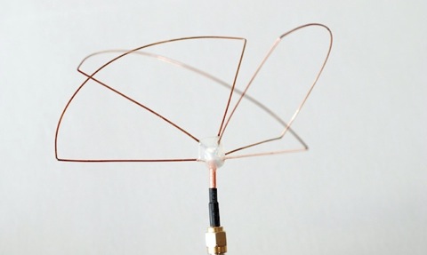
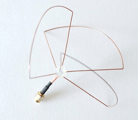
The Cloverleaf is a closed-loop antenna, meaning that the signal and ground wires are connected. Measuring between signal and ground with a multimeter would read a short circuit. However it works great as an antenna. The cloverleaf has 3 lobes at 120° apart from each other in the horizontal plane and angled 45° in the vertical plane. It may look funky, but it’s an excellent transmitter antenna. In fact its one of the best FPV video transmitter antennas out there at the moment.

The Cloverleaf is best suited for the transmitter, and almost exclusively used for this purpose. It has an excellent radiation pattern and very low gain. It’s also possible to achieve a perfect 1.0 SWR, making it very efficient. It is not the ideal antenna to use on the receiver though. The reverse polarization rejection pattern is very erratic and varies between -8 and 19dBi. Therefore there are better antennas to choose for the receiver. This doesn’t matter for transmitting signals though, only for receiving them.
Gain: 1.2dBi
Lowest SWR possible: 1.0
Directionality: Omnidirectional
Difficulty to make: High
Best suited for: Video transmitter only
Downsides: Hard to make, comparably fragile, big, not very aerodynamic, not possible to trim to the right frequency.
Upsides: Possible to achieve SWR of 1.0, pretty wide band, good radiation pattern, low dBi
You need:
Stiff wire that is easy to solder.
RG316 coax cable.
(The antenna on the pictures in this guide is left hand polarized)
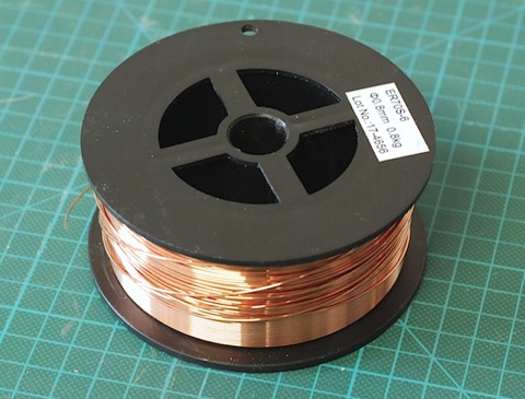
I use 0.8mm copper plated MIG welding wire. It’s stiff and holds its shape well. Yet it’s not to hard to work with in terms of bending and shaping and it’s really easy to solder. Therefore a good choice.
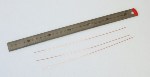
Start of by straightening the wire. Then using a wire cutter, cut 3 pieces of wire a little longer than the calculated length you got from the calculator above. Sand the ends of the wires down using sandpaper, a dremel or a file to the exact length. This technique is the best I’ve tried as trying to cut the wire to the exact right length with just a wire cutter is nearly impossible. Plus it doesn’t make a clean cut. Cutting a little longer than sanding it makes the ends nice and clean.

Now we are going to bend both ends 90° inwards creating a “U” shape with a flat bottom. The length at which you are going to bend is 1/4 wavelength from the ends of the wire, and can be calculated here:
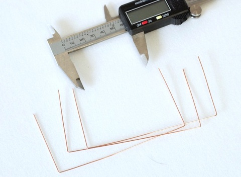
The three “U” shaped pieces
A tip on how to get good precision and speed up the bending is to use pair of calipers. Set the caliper to the length you wish to bend but subtract half the thickness of the wire. So if you’re going to bend at 59.96mm then set the calipers at 59.56mm if you’re using a 0.8mm wire. Place a pair of pliers on the inside of the calipers measuring arm and grab the wire and bend it. Perfect results every time.
Now it’s time to create the arc. The easiest way is simply using your hands and bend it to the right shape. The two tips should meet at a ~105° angle. They could not and should not meet at 90°.

Here is the ~105° angle visible. Be careful to make the curve as uniform and well shaped as possible.

Repeat with the two other wires as well.
Now it’s time to strip the coax cable. I highly recommend using RG316 as it’s much more heat resistant than RG58. Soldering this antenna can be quite a challenge and you don’t want the coax to melt on top of everything. Separate the shield into 3 pieces and place them at 120°. Strip the signal as close to the shield as you dare. If this part is to long it’s going to shift the frequency of the antenna. But be sure that the signal and shield can’t connect.

To simplify the soldering I made a simple jig out of food container lid. I simply taped down the lobes at 120° apart. Also make sure that the lobes are at 45° vertically (see video at the end of the guide for more detailed illustration). I recommend using “poster gummy” (green mass used to fixate posters to walls without using nails). It holds the lobes in place better and is easier to work with, but I didn’t have any at home at the time of this build. Notice the hole in the bottom. That is where the coax cable is fed through and soldered in place.
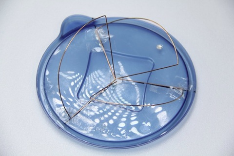
At this step you also decide which polarization the antenna is going to be. The picture shows a left hand polarized clover. For right hand polarization, simply flip the elements over to the right instead.

Solder the legs to the shield first. Be sure to get it properly soldered. Pre-tin both the wire and the shield. Use extra solder flux if you have any.
The trickiest part of the whole thing is to solder the 3 legs to the signal wire. I usually bend the lobes so that they align perfectly without having any strain on them while soldering. This eliminates the risk of one “plonking” off while soldering. An other technique is to use “helping hands” to hold the wires in place. Just make sure to pre-tin all wires and get a good solid solder joint. This is the part that’s most likely to break on this antenna and if it’s a cold solder joint, it’s going to break really easy.
Check all your angles now. The 120°, the 45° and when looking straight from above the top there should be a 10° separation between the legs thats soldered to the feed-point and the legs soldered to the shield. (See video at the end.)
I added some hotglue to support the solder joints so that they don’t fatigue or break as easy. Beware that hotglue will shift the resonance frequency slightly. But in my opinion, it’s a small price to pay for added durability.
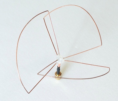
Really neat looking antenna. People will think you know what you’re doing if you use on of these.
This antenna was measured to 1.05 SWR which made me really happy.

It’s hard to photograph properly but the top of one lobe and the bottom of the next are 10° apart. (See video instead!)
Here is a video showing the geometry of the Cloverleaf antenna by Jayzy74
Observe that this video shows a right hand polarized antenna, while the previous pictures in this guide are of the left hand polarized version.
The key to success when making FPV antennas is to be meticulous. The more accurate you can make the antenna the better it will perform. Take your time and don’t rush things. This antenna is well worth the effort.
Hello, i can’t sheck the value for 5800Mhz.
Can you help me?
Pleasure.
Simply type in you frequency, example 5.8 Ghz as “5800”
drop the cursor into the length text box an when you click to drop, the number will appear. Looks like a GUI bug.
The calculator is no longer working any more! I think that David disable it… kind of sad… but i guess that he get tired of giving and no body giving back! Sad,Sad, Sad…
Have some patience. It’s on the list to fix. Still have about 20 things on the list to fix on the website 😀 Getting to it soon.
The Calculator for the wire length and the bends isn’t working for how to make a clover leaf antenna……..Did you disable it or is it my computer
also not working for me.
Maybe someone could post 5.875ghz measurements?
hello, have a date for when going back to work the calculator? or will not go back to work anymore?
The Calculator isn’t working.you disable it?I tried it with different browsers.thanks…
You can get the measurements here and there’s a formula for calculating them also.
http://www.rcgroups.com/forums/showthread.php?t=1388264
use calculators on this site:
http://flitetest.com/articles/Cloverleaf_Antenna
thank you very much…
thank you very much
Hi all,
Can I use 0.8mm wire for a 5.8 ghz antenna or do I need 0.6mm?
very good!Thank you very much!
Can you send the length calculation software to my email([email protected])? Thank you very much!
What do you suggest to do about the thickness of the coax? When I solder the ends right up to the coax, the thickness of the coax is not precise, and changes thing significantly. Is this significant?
also not working for me.
Maybe someone could post 5.875ghz measurements?
The Length of wire is 52.6mm and the bend is 13.1mm.for 5875mHz
5.705 = wire length 53.81mm
bend at 90Deggre = 13.45mm
i want to build a 900mhz cloverleaf antenna
not sure how to get measurements
Go to flitest on youtube in the description you can got to their web sit and look up FPV antennas………..you will find all the info you need.
the calculator is not working for me either,could someone please give me the measurements for 900mhz on channel 3. thanks!!
use calculator on this site
http://flitetest.com/articles/Cloverleaf_Antenna
The calculator is working now 🙂
I build this antenna, but when I tested it i blew up my FOX 800A. How is this possible, the signal and ground are connected like you mentioned in your discription.It doesn’t work with normal antenna’s anymore. Does anyone has the same problem?
By my calculations, the angle should be closer to 115 degrees, not 105 degrees?
5.8gHz antenna:
Wire length: 52.9
Bend at: 13.23
Angle:
52.9-(2×13.2)=26.4mm
Radius: 13.2
circumference: 83.9mm
83.9/360=0.23mm (1 degree)
115×0.23=26.5mm (115 degrees)
I created a tool to make a 5800Hz antenna. Find it here: http://www.thingiverse.com/thing:780287
For 5800, how long does the round part of the antenna have to be?
Awesome guide!
I’m about to make my own CL antenna for my 5.8G FPV system, but I have two questions:
1. Does the length of RG316 matter?
2. Is it okay to use ER50S-6 instead of ER70S-6?
Could anyone kindly help?
Thanks in advance.