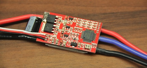
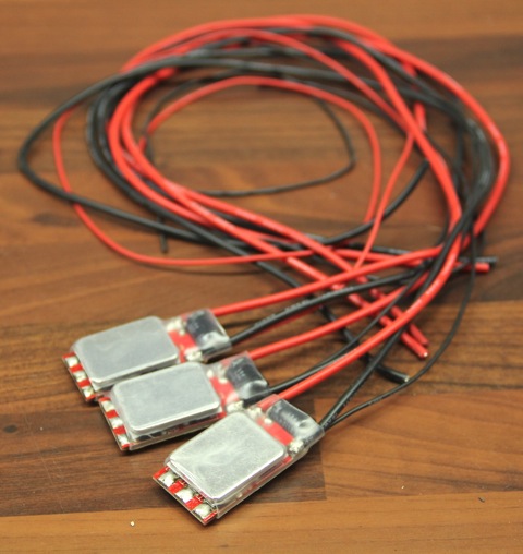
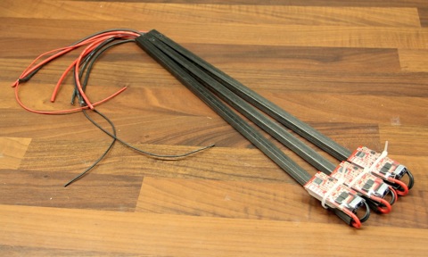
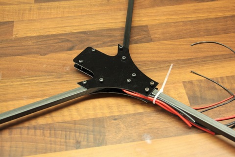
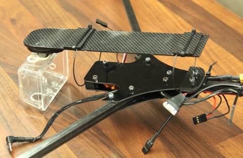
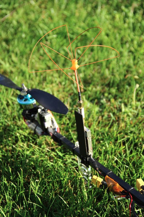
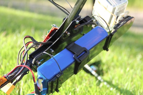
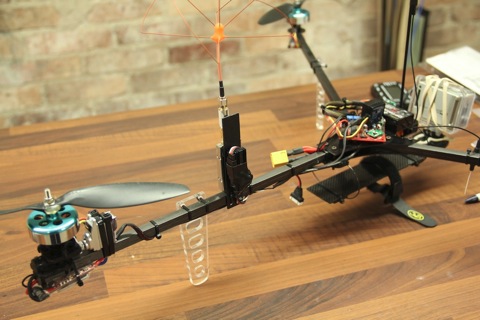
Let me present the next evolution in my tricopter adventure. I call it the Tricopter V2.6HV where HV stands for High Voltage. This version uses a 4S LiPo battery, shorter arm and smaller props to achieve increased stability, improved maneuverability and almost no wobbling during decent.
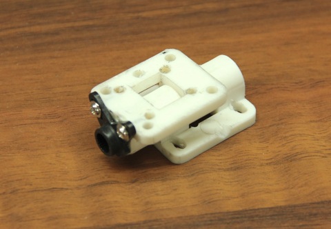
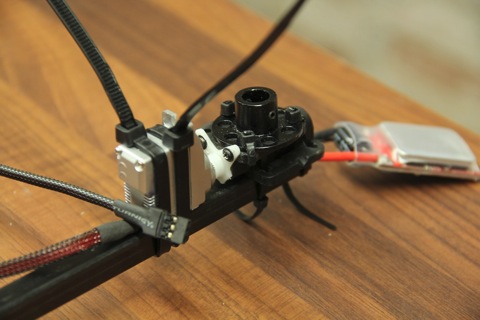
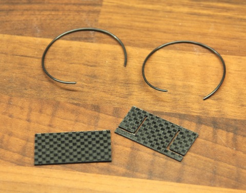
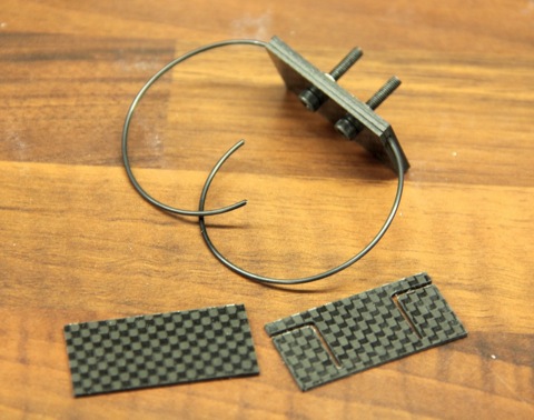
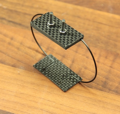
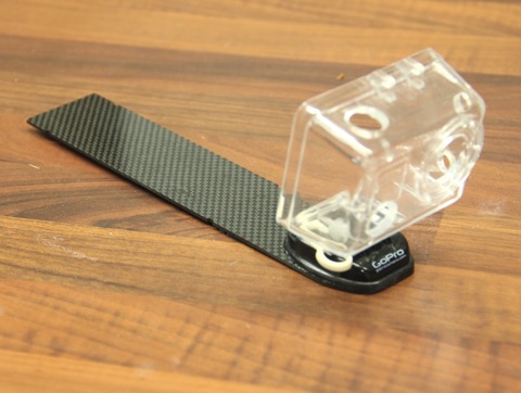
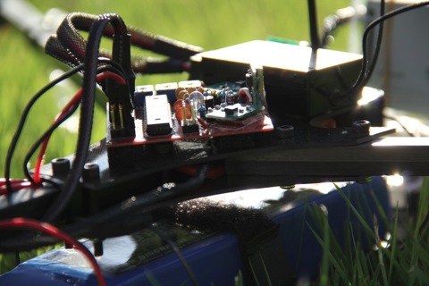
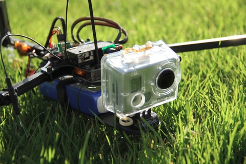
In this version I will present a whole new vibration dampening system, that works so well that even with relatively heavy vibrations it still produces silky smooth video.

Click here to get to the first part of the build log