
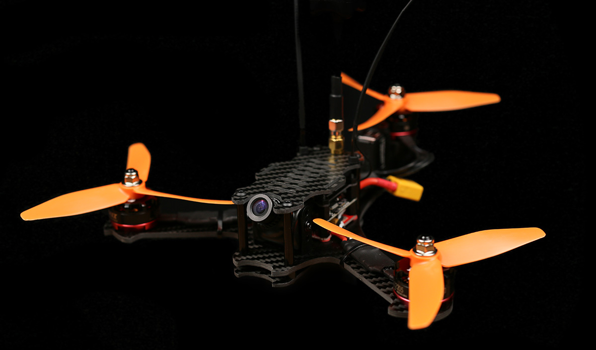

Time to build a Baby Tricopter. This is a 170mm motor to motor crazy 7:1 thrust to weight ratio beast of a tricopter. It’s small and durable and a real blast to fly. So lets get started.

I’m going to built this baby tricopter (with F3FC + BabyPDB) together with the baby tricopter electronics pack.

Before we start mounting stuff, I highly recommend finishing off the carbon fiber in the kit. There is a crescent shaped diamond file included in the kit for this purpose. File the edges lightly. Wear breathing protection and be outside when doing this. Carbon fiber dust in pretty nasty stuff.

Be sure to get the holes as well.
The reason why you should do this is mainly that the edges become smoother (duh), this keeps zip ties from snapping prematurely, tape wrapped around things last longer, battery/camera straps lasting much longer and recedes the chance of you cutting yourself when handling the copter.

Now we can mount the BabyPDB using the 10mm long nylon screws, fiber washers and standoffs.

The fiber washers are there to keep the BabyPDB from touching the frame. There is no exposed pads or anything on the bottom so it should be fine touching the carbon, but better be safe than sorry.
Mount the board with the large pads towards the tail.

You’ll be needing a pigtail with the battery connector you plan on using. I’m using the 5cm XT60 pigtail, which I stripped back a bit to get more surface contact on the pads.

Soldered in place.

To get a bit more speed and torque from the BMS210 feedback servo, I bridged the 6V pads on the BabyPDB to get it to output 6V instead of 5V.

Screw the nylon standoffs down to hold the board in place.

Mounted in place. 
The wire on the BMS210 feedback servo is quite a bit too long, so we’re going to steal a piece to use to connect the PDB to the flight controller.
That length looks about right.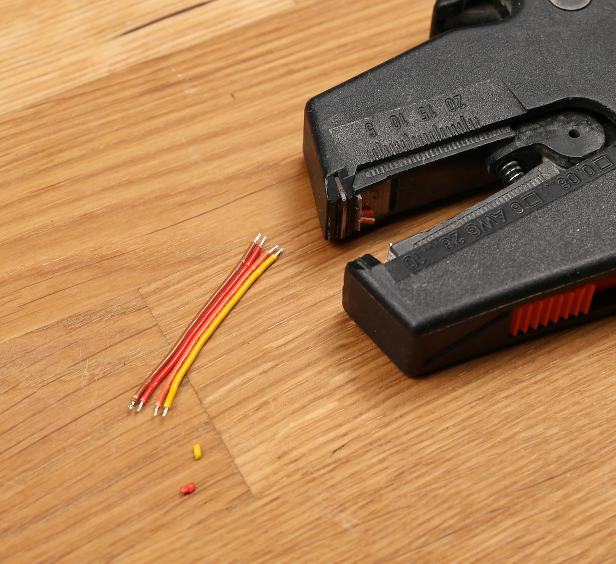
Strip and tin.

I connected the red wire to the BEC+ output, the brown to GND, the orange to ISENSE (current sensor) and the yellow to VBAT (raw battery voltage)

Picture of the bottom of the PDB for reference.
Solder the wires to the correct pads on the flight controller. The pads are quite clearly marked.

If you plan on powering anything power hungry through the flight controller I recommend moving this resistor over to the “BEC” position. This will bypass the built in 5V regulator on the flight controller. Instead the BEC voltage will power the board and all pads marked “5V” will output the BEC voltage.
So for instance if you plan on powering RGB LED’s through the board, I highly recommend doing this.

Now we’re going to do the tilt mechanism.
If there is any hint of the tilt having any friction, lightly sand the pieces until it’s buttery smooth. 
If the screw is causing friction, try screwing it a ton of turns. The threads should wear down the plastic some and reduce the friction.

Strap down the tilt using two zip ties.
Mount the zip ties so that the “knots” face the opposite direction.

Looks pretty good.

Mount the servo block in the grooves. If the block doesn’t sit all the way down flush, use the included file to remove a small amount of plastic. You want it to lay flat against the bottom.

Strap down the servo. You’ll be needing 2 zip-ties connected together to reach all the way around the servo. This also gives better strap down force as you have 2 places to apply force. Again alternate the “knots” not to get all force on one side. The groves for the tilt block extend backwards which will let you slide the servo back later when doing the servo alignment.

Time for the motors and speed controllers. 
The front two motors you can strip the wire really short for a clean and light setup. If you don’t like doing that you can always keep the long wires and fold them back over the ESC.

Baby tricopter electronics kit include thick black heat shrink lined with a kind of hot glue. When shrunk the hot glue melts and if you squeeze the edges properly when the heat shrink is still hot, the ESC’s will be water resistant and very durable.

The back motor and ESC assembled a bit differently than the front 2.

The full length of the wires should be used, and they should be soldered on at an angle.

Shrink some heatsink over it and squeeze the edges.
To screw down the motors use the included 6mm long screws. If you use longer screws you might damage the motor windings and smoke your motor and ESC. Always use blue locktite when screwing anything metal into metal.

I mount my motors using 2 screws instead of 4. This reduces the weight a bit. If the threads were to strip in a crash I can always mount the motors using the 2 holes that were unused before.

One thing you really don’t want on any multi rotor is components moving around during flight, as this can create unwanted input to the gyro, making your copter fly bad.
Double sided foam tape is a great thing to put underneath your ESC’s before strapping them down. It helps keep them in place as well as gives some dampening, which protects the ESC in a crash.

Strapped the ESC down with a zip tie. You can also use electrical tape or similar.
Now mount the back motor.
Screw it in place, but remember to mount it so that the wires comes out this way.
For clarity, this is the way you want the wires to come out.

This is so that there is plenty of slack in the wire to allow for smooth, unhindered moment throughout the whole servo range. You can also see in the picture why we soldered the wire at an angle. Things get tight otherwise.
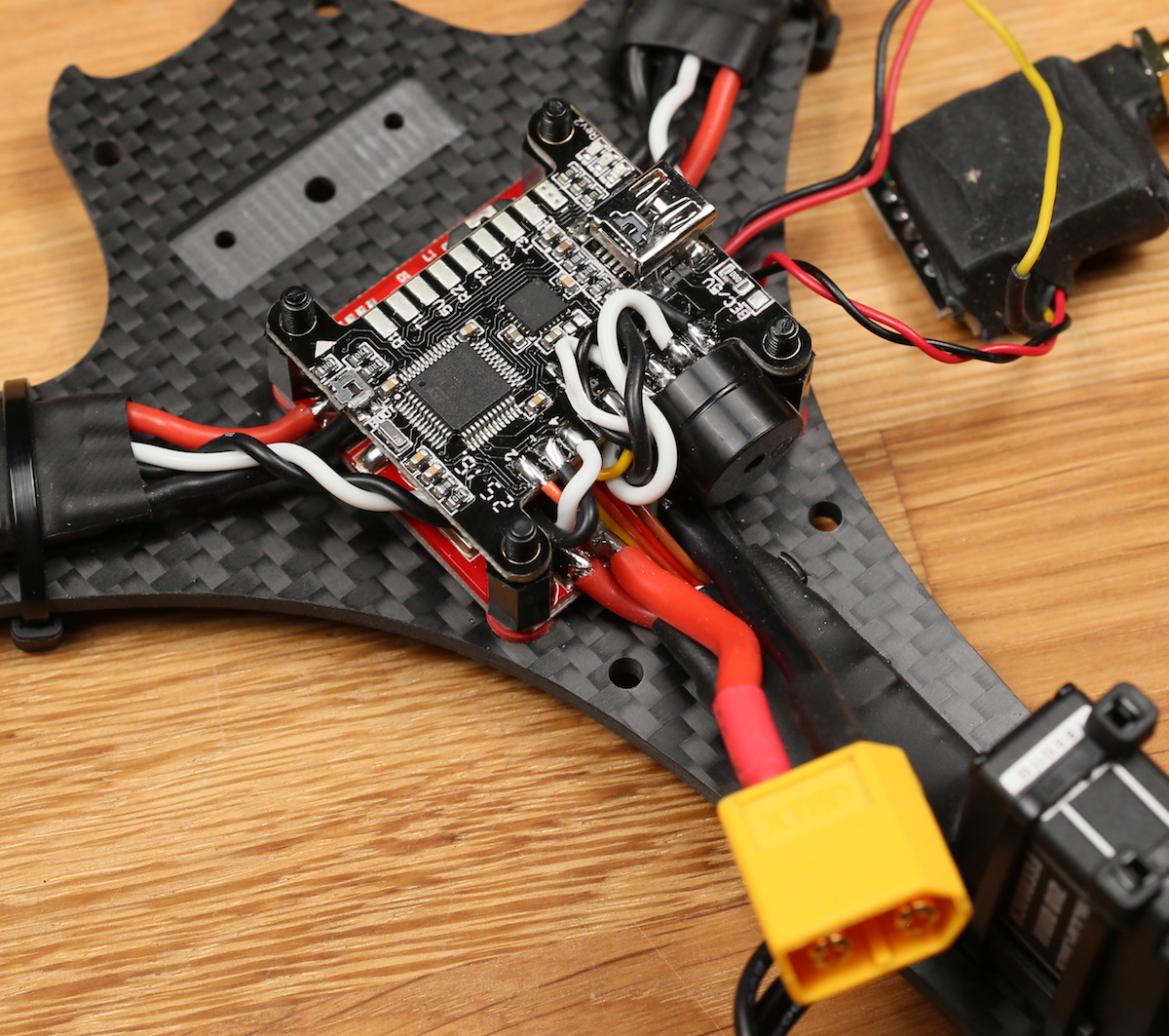
Looks like a rats nest at the moment. We’ll start cleaning that up now.
The back ESC should be soldered to the back ESC pads. Do not solder the ESC wires to the battery connector pads as this will bypass the current sensor and your current draw and mAh draw will be off by around 33%.
The left ESC needs to have the red wire shortened and soldered to the + side of the PDB.

The right ESC is the opposite. The black wire needs to be shortened.

I’ll be using a X4R-SB receiver from FRSKY. I’ve removed the pins and directly soldered some servo wires to the SBUS output and kept the SPORT wire.

To protect the receiver I’m going to use some liquid electrical tape. It’s fantastic stuff which makes stuff water resistant and creates a rubbery kind of coating. If you plan on using it I highly recommend testing that the receiver works properly before putting the stuff on. It’s a real pain to get off. It’s also a good idea to take a picture of the top and bottom side of the board just in case something doesn’t work, you can go back and inspect your work.
The reason why I’m using the X4R is that I had one laying around. If I would built another copter I would use the XSR receiver, which is smaller and lighter and fits in the stack without modification.
Once dry I added some thin heat shrink.
Will solder the receiver to the flight controller in a bit.

While we have good access to the power pins we might as well solder in the FPV system. I’m using a HS1177 camera and a Eachine TS5840 with a 90° antenna connector mounted on this build. Not super happy with this video transmitter though. Will probably switch it for a TBS Unify pro HV, which is a much better quality.

Soldered the signal wire between the camera and video transmitter.
I’ll be powering the camera via the 6V BEC on the BabyPDB. This will take load of the built in 5V regulator on the video transmitter, which will keep the video transmitter a lot cooler. The BabyPDB BEC also has a cleaner output as well as it protects the camera from voltage spikes. The video transmitter I’ll be powering straight from the flight battery.

I soldered the video TX + to the VBAT pad. The – to GND, the camera + to the BEC+ pad and the camera – to GND.

Schematic. The reason why I don’t power the video transmitter from the built in BEC on the BabyPDB is that the minimum operating voltage on the videoTX is 7V. If you have a VTX that can handle 6V I recommend powering it from the BEC as it will significantly reduce the heat generated in the VTX.

It’s a great idea to have a beeper hooked up to your flight controller. This will greatly help when doing the tail tune and it will also help you find your copter when you crash it in tall grass and such.
To keep things simple I decided to solder it straight to the board. You don’t have to do it this way. You can just as easily use some wire to get it away from the board.
I bent the – pin of the beeper to 90° at the base and then 90° again further down to be able to reach the pads.
Now we can start soldering signal wires to the board. The red and brown servo wires are connected to the pins on the edge labeled BEC + and GND. This will power the servo with the 6V from the babyPDB.
The orange servo wire is soldered to the pad labeled number 2 and the yellow to the “FB” pad. If you’re using a servo that doesn’t have a servo feedback wire you only need to solder the servo signal wire to the “2” pad.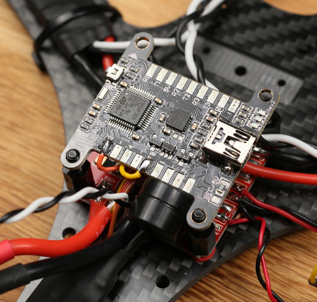
Closeup of the soldering for extra clarity.
Now the ESC wires. This is the way the signal wires should be connected:
Pad number 1 = Tail motor
Pad number 2 = Servo
Pad number 3 = Front Right motor
Pad number 4 = Front Left motor


All the black wires should be soldered to pads marked “-” This is important as the ESC’s might act weird otherwise.
All hooked up.
Time to connect the receiver. I connected my receiver in the following way; – to -, + to +, SBUS output to R3 (RX pin on UART3) and SPORT to T2 (TX pin on UART2). Also mount the nylon standoffs at this point.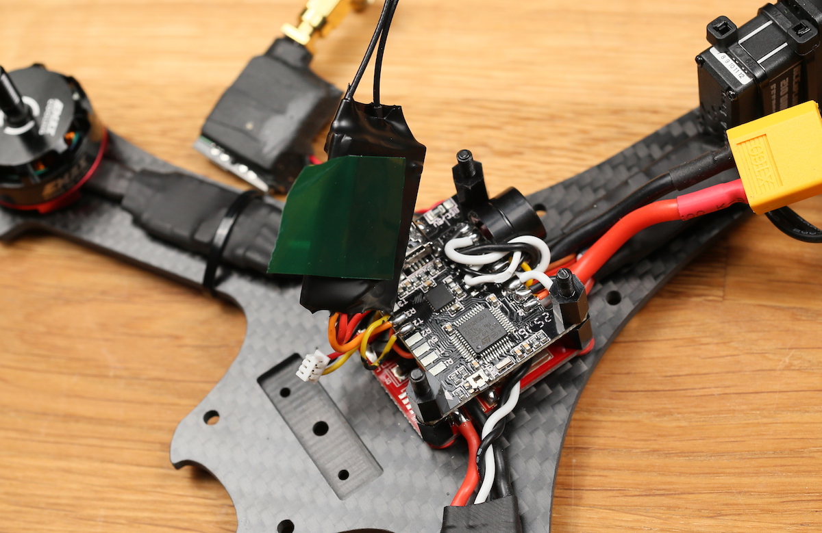
Some double sided foam tape to mount the receiver with. It’s also going to get squished down by the transmitter plate, holding it firmly in place.
Mounted.
Use a zip tie to mount the video transmitter to the transmitter plate.
Mount the transmitter top plate using the M3 nylon nuts.
Mounting the camera is really simple. The bracket that is included with cameras such as the HS1177 and the Runcam Swift fit into the milled down grove. This grove prevents the mount from turning and holds it firmly in place.
Use a 6mm screw to mount it. If you’re using a Runcam swift use the 2mm screws that comes with it to mount it. You might need to file slightly on the HS1177 bracket as the manufacturing tolerances on those brackets are far from perfect.
Use a m3 lock nut on the bottom.
Look at that fanciness.
The camera angle can easily be changed. If you think the angle is changed too easily you can always add some thin double sided tape on the inside of the bracket, but I’ve never needed it.
The bracket really is super light and pretty a pretty clean solution.
Now we’re going to mount the bottom and top plate.
The kit includes some nylon standoffs. Place these over the 4 holes that are still unused.
Place the bottom plate on top of them.
Use the 14mm long screws and shove them through the spacers and the unibody frame.
Screw on the 30mm aluminium spacers.
Mount the top plate using 4 6mm long m3 screws.
The top plate has slots in it to fit both GoPro and Runcam 2 form factor cameras. If you’re not running a camera on the top plate you can mount the battery there instead of on the bottom if you wish.
Time to mount the antennas. To do this we’re going to use some good old zip ties.
The top plate has slots for mounting these zip ties. Just slip them through and tighten them down.
Closeup of the zip tie mounting.
Slide over some heat shrink over both the zip tie and the antenna wire.

The heat shrink shouldn’t be too big. It should be able to shrink nice and snug around the zip tie and antenna.
Shrunk down.
Congratulations! The build is now done! Don’t forget to load the firmware onto the board and do all the setup. This process is the exact same as on the Tricopter V4 and Mini Tricopter, so you can look on the setup videos for either and set this thing up without any problem.

Also don’t forget to do the tail tune setup.


This is one crazy fast and super agile tricopter. I really look forward to seeing your builds and FPV videos! Please post them in this section of the forums. Good luck with your build!
Leave a Reply
You must be logged in to post a comment.