Author: RCExplorer – David

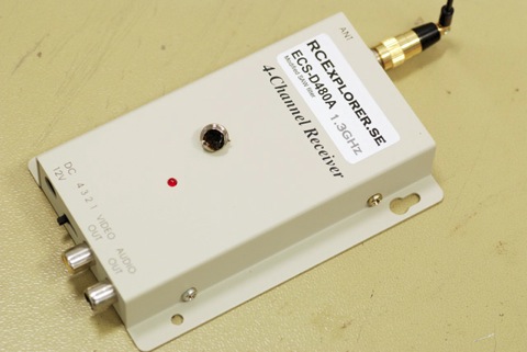
  • Exchanging the SAW filter in a 0.9/1.3GHz receiver for a better one

    Exchanging the SAW filter in a 0.9/1.3GHz receiver for a better one

    This modification requires advanced soldering skills as well as a powerful soldering-iron.

    The RF tuner in the 900MHz and 1.3GHz receivers are originally designed for satellite receivers and have a pretty wide bandwidth compared to what’s needed. So why is having a wide bandwidth bad? All bandwidth not used leads to RF noise that reduces the receiver sensitivity, which means shorter range.

    Inside of the video receivers there is a SAW bandpass filter. This filter is located in the intermediate frequency (I.F) stage in the RF tuner and it determines the video bandwidth. The original SAW filter in one of these RF tuners are 27MHz wide. For transmitting video and audio about 14MHz of bandwidth is needed. By exchanging the SAW filter to one that has narrower bandwidth the signal to nose ratio can be greatly increased, which means longer range and better quality.


    I will be using a ESC-D480A SAW filter which has a bandwidth of 17MHz. It’s easy to come by, cheap and well tested by others for this mod.


    Start by unscrewing the 4 screws on the sides of the box. Desolder the RF tuner. A good tip is to mark the cables so you know where to reattach them later on.


    Remove the top and bottom lids, they’re just clamped on.


    The SAW filter is the big round one with lots of solder on it. The filter has three pins and the top is soldered to ground. You need a powerful soldering-iron for this as the whole bottom of the PCB is a ground plane which loves to suck up heat.


    Suck out the holes and clean of any flux residue before you pop in the new filter.


    Solder the new filter in place.


    Make sure to clean the PCB after you’re done, you don’t want any flux or dirt left.


    Done! It’s as simple as that.

    This mod gives an increased sensitivity of about +3dBi! That’s the same as doubling your transmitter power!

    (This modification does not work on 2.4/5.8GHz receivers, they are equipped with a 17MHz SAW filter stock)

    I’ll report back when I’ve had the chance to try it out thoroughly.

  • I’m back in business

    Yeah! My hand is finally healed! (for those who forgot read this) The great news is that I don’t have to have surgery. The finger healed in the right direction and I can now use it again. Sorry for the lack of updates but I do promise a treat for you very soon.

  • Octocopter progress

    I’ve made some progress on the Octocopter build. I’m currently building a two axis camera gimbal that’s going to be stabilized thought the MK flight controller.
    octo46
    More pictures on the project page

  • FY21AP + AP117

    Remember my disqualification from FPV-community’s competition? I have some great news, Feiyu Tech thinks I deserve a FY-21AP and AP117 OSD and so they sent me a package to review.
    It arrived yesterday and here are the first pictures:
    FY21AP1
    Nicely packaged in plastic cases. (more…)

  • KK-Quad X setup guide

    KK-Quad X setup guide

    A few words before we start:
    To get the best stability and flight performance from your KK-controller mount it using a vibration dampening material such as “gyro-tape” or a thick double sided sticky tape. Also make sure to balance you props and motors to remove as much vibrations as possible.

    Some general multirotor tips:
    Do not use bigger propellers than you need. Light propellers gives faster response resulting in a more stable platform.
    When designing your platform try to get it to hover around mid-stick. This means that your platform will have enough power at all time to respond and compensate but not have to much power resulting in a less stable platform. To achieve this use bigger/smaller propellers, lower/higher kV motors, more/fewer number of battery cells or more or less weight.

    Safety:
    Never have the propellers mounted when setting up your platform! A spinning motor without a prop isn’t dangerous but a prop spinning at wide open throttle cut’s flesh better than a hot sword. Therefore, never ever have the props attached when you’re setting up or making adjustments to you multi-rotor platform.
    inkoppling
    Hooking up your KK-board:
    Receiver:
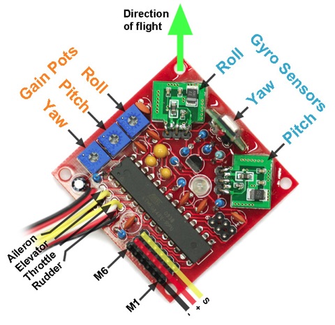
    The soldered cables coming of the board are the four signal wires that plugs into your receiver.
    On a Futaba/Hitec receiver they plug in as follows:
    Aileron – Channel 1
    Elevator – Channel 2
    Throttle – Channel 3
    Rudder – Channel 4
    On a Spectrum receiver simply plug the aileron into the aileron port, elevator to elevator and so on.

    Motors/ESC’s:
    Down in the corner there are 6 motor outputs (M1 through M6)
    On a Quadcopter-X the ESC’s are plugged in as such:
    M1 – Front left motor CW
    M2 – Front right motor CCW
    M3 – Back right motor CW
    M4 – Back left motor CCW
    motorsQUADX
    Preparing the transmitter:
    Create a new model memory and make sure that all mixes are disabled, all trims are neutral and that all End Point Adjustments (EPA) and D/R’s are set to 100%

    If you have a computer-radio you can chose either airplane or helicopter mode. It doesn’t really matter. The helicopter mode will have the advantage of setting a custom throttle curve for those who doesn’t like a linear response on the throttle. If you use the helicopter mode make sure that the swash is set to; two servos 90°. If you use 120° CCPM mixing your platform will be unflyable!

    Arming and disarmed the flight-controller:
    The flight-controller has a built in safety feature which disables the throttle stick. This is a great feature that probably will save your platform or face at least once.

    The KK-board will on power up be in the “locked”/disarmed position. The LED on the board indicates if the board is armed or not.
    LED off = “locked”/disarmed, LED on = Armed.
    To arm the board move the throttle/rudder stick down to the right corner and hold it there for about 5 seconds. The LED will turn on indicating that the board is armed and ready. To unarm/lock the board again move the throttle/rudder stick down in the left corner for 5 seconds.

    Step by step setup guide:
    1. Check if the throttle stick
    This is to ensure that the throttle stick is moving the right direction and have enough trow to initialize the flight-controller.
    Never perform this step with the props mounted!

    – Turn on the transmitter and then the flight-controller
    – Move the throttle/rudder stick to the down-right corner
    – The LED should turn on, if it doesn’t:
    – Try adding a bit of “down” trim on the throttle channel
    – Try increasing the EPA on the throttle channel
    – Try reversing the throttle channel

    2. Calibrating the throttle range on the ESC’s
    This is to ensure that all the ESC’s have the same throttle range end points. This step only needs to be performed once. Fail to do this calibration can result in an uncontrollable platform. If you ever install new ESC’s this step needs to be performed again.
    Never perform this step with the props mounted!

    – Make sure that the flight-controller is turned off
    – Turn the Yaw pot to the MIN position
    – Turn on the transmitter
    – Move the throttle stick to top (full)
    – Turn on the flight-controller
    – Wait until the ESC’s beeps twice after the initial beeps. (Plush and SS ESC’s)
    – Swiftly move the throttle stick fully down (closed). The ESC’s beeps
    – Power off the flight-controller
    – Restore the yaw pot to around 50%
    RPY

    3. Checking the direction of the transmitter channels
    This step is to ensure that the sticks actually perform the action in the way that they are supposed to.
    Never perform this step with the props mounted!

    – Turn on the transmitter and then the flight-controller
    – Arm the controller. (Move the throttle stick to the down-right corner)
    – Start the motors by raising the throttle (around 1/4 or so)
    – Move the Pitch (Elevator) stick on the transmitter forward. The two back motors (M3,4) should speed up. If it doesn’t, reverse the channel in your transmitter.
    – Move the Roll (Aileron) stick to the left. The two right motors (M2,3) should speed. If it doesn’t, reverse the channel in your transmitter.
    – Move the Yaw (Rudder) stick to the left. Motor M1 and M3 should speed up. If it doesn’t, reverse the channel in your transmitter. (You ought to have noticed this before as this would also mean that the arming function was reversed)

    4. Checking the gyro compensations
    This step is to ensure that the gyros compensate in the right direction. If they don’t the platform will be uncontrollable and flip heads over heals.
    Never perform this step with the props mounted!

    – Turn on the transmitter and then the flight-controller
    – Arm the controller. (Move the throttle stick to the down-right corner)
    – Start the motors by raising the throttle (around 1/4 or so)
    – Tilt the Quadcopter-X forwards. The two front motors (M1,2) should speed up. If it doesn’t, note it, you’ll fix this in the next step.
    – Tilt the Quadcopter-X to the right. The two right motors (M2,3) should speed up. If it doesn’t, note it, you’ll fix this in the next step.
    – Rotate the Quadcopter-X to the right (clockwise). Motors M1 and M3 should speed up. If it doesn’t, note it, you’ll fix this in the next step.

    5. Revering the gyros
    This is how you reverse the compensation direction of the gyros

    – Make sure that the flight-controller is turned off
    – Turn the Roll pot to the MIN position
    – Turn on the transmitter then the flight-controller
    – The LED will flash rapidly 10 times and then turn of
    – Move the stick for the gyro you want to reverse. (If you want to reverse the roll gyro, move the roll (aileron) stick)
    – The LED will flash continually to confirm your choice
    – Turn of the flight-controller
    – If more gyros needs to be reversed, turn on the flight-controller and repeat the process. If you’ve reversed all the gyros you want, restore the pot to 50%

    6. Reversing the pot direction
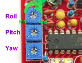
    If you think that the pots turn in the wrong direction you can reverse the direction. This will mean that the MIN and MAX in the picture above will be inverted.

    – Make sure that the flight-controller is turned off
    – Turn the Roll pot to the MIN position
    – Turn on the transmitter then the flight-controller
    – The LED will flash rapidly 10 times and then turn of
    – Move the throttle stick for the to the top
    – The LED will flash continually to confirm
    – Turn of the flight-controller
    – The pots have now been reversed. If you wish to reverse the pots back you need to turn the Roll pot fully to the other extreme and repeat the process. Otherwise restore the pot to 50%

    Final adjustments:
    – Make sure that all pots are set at 50% (in the middle)
    – Make sure that the CG of your platform is correct
    – Make sure that all the D/R’s are at 100%

    Liftoff procedur:
    – Place the platform on a plane surface
    – The platform should be motionless before takeoff
    – Arm the controller by moving the throttle/rudder stick down in the right corner for 5 seconds or so
    – Raise the throttle and fly. The gyros calibrate just as the throttle stick leaves the minimum position

    Finding the correct gain:
    – Increase the gain in small steps until the platform starts oscillating (overcompensating making the platform rock from side to side)
    – Reduce the gain a bit
    – You now have the optimum amount of gain.
    – Fast forward flight requires lower gain.
    – Too low gain is recognized by a hard to control platform that wants to tip over.
    – Too high gain is recognized by oscillations.

    EPA, D/R and EXPO:
    If the platform feels to fast or twitchy you can either reduce the EPA’s (End Point Adjustment) or D/R’s (Dual Rates) or add EXPO (Exponential)
    EPA and D/R makes the whole stick less sensitive and makes the platform “slower”. EXPO makes the middle of the stick less sensitive but keeps the throw at the end of the stick. This means that you can have nice control in a hover, which requires small adjustments, but you keep the ability to fly fast and agile.

    – It’s not uncommon to need a couple of clicks trim to make the platform hover perfectly leveled. This is due to the small differences in the motors, ESC’s and props.

    – Always disarm the platform after you’ve landed. (Move the throttle stick down in the left corner for 5 seconds or so) This little procedure has the potential to save you platform or face, so be sure to make it a habit.

    Good luck!

  • KK-Tricopter setup guide

    KK-Tricopter setup guide

    RCEKK1
    A few words before we start:
    To get the best stability and flight performance from your KK-controller mount it using a vibration dampening material such as “gyro-tape” or a thick double sided sticky tape. Also make sure to balance you props and motors to remove as much vibrations as possible.

    Some general multirotor tips:
    Do not use bigger propellers than you need. Light propellers gives faster response resulting in a more stable platform.
    When designing your platform try to get it to hover around mid-stick. This means that your platform will have enough power at all time to respond and compensate but not have to much power resulting in a less stable platform. To achieve this use bigger/smaller propellers, lower/higher kV motors, more/fewer number of battery cells or more or less weight.

    Safety:
    Never have the propellers mounted when setting up your platform! A spinning motor without a prop isn’t dangerous but a prop spinning at wide open throttle cut’s flesh better than a hot sword. Therefore, never ever have the props attached when you’re setting up or making adjustments to you multi-rotor platform.
    inkoppling
    Hooking up your KK-board:
    Receiver:
    The soldered cables coming of the board are the four signal wires that plugs into your receiver.
    On a Futaba/Hitec receiver they plug in as follows:
    Aileron – Channel 1
    Elevator – Channel 2
    Throttle – Channel 3
    Rudder – Channel 4
    On a Spectrum receiver simply plug the aileron into the aileron port, elevator to elevator and so on.

    Motors/ESC’s:
    Down in the corner there are 6 motor outputs (M1 through M6)
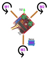
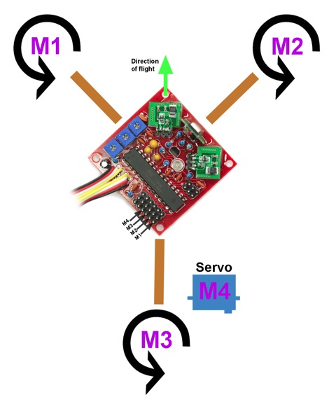
    On a Tricopter the ESC’s/servo is plugged in as such:
    M1 – Left front motor
    M2 – Right front motor
    M3 – Back motor
    M4 – Tail servo
    motorsTRI
    Preparing the transmitter:
    Create a new model memory and make sure that all mixes are disabled, all trims are neutral and that all End Point Adjustments (EPA) and D/R’s are set to 100%

    If you have a computer-radio you can chose either airplane or helicopter mode. It doesn’t really matter. The helicopter mode will have the advantage of setting a custom throttle curve for those who doesn’t like a linear response on the throttle. If you use the helicopter mode make sure that the swash is set to; two servos 90°. If you use 120° CCPM mixing your platform will be unflyable!

    Arming and disarmed the flight-controller:
    The flight-controller has a built in safety feature which disables the throttle stick. This is a great feature that probably will save your platform or face at least once.

    The KK-board will on power up be in the “locked”/disarmed position. The LED on the board indicates if the board is armed or not.
    LED off = “locked”/disarmed, LED on = Armed.
    To arm the board move the throttle/rudder stick down to the right corner and hold it there for about 5 seconds. The LED will turn on indicating that the board is armed and ready. To unarm/lock the board again move the throttle/rudder stick down in the left corner for 5 seconds.

    Step by step setup guide:
    1. Check if the throttle stick
    This is to ensure that the throttle stick is moving the right direction and have enough trow to initialize the flight-controller.
    Never perform this step with the props mounted!

    – Turn on the transmitter and then the flight-controller
    – Move the throttle/rudder stick to the down-right corner
    – The LED should turn on, if it doesn’t:
    – Try adding a bit of “down” trim on the throttle channel
    – Try increasing the EPA on the throttle channel
    – Try reversing the throttle channel

    2. Calibrating the throttle range on the ESC’s
    This is to ensure that all the ESC’s have the same throttle range end points. This step only needs to be performed once. Fail to do this calibration can result in an uncontrollable platform. If you ever install new ESC’s this step needs to be performed again.
    Never perform this step with the props mounted!

    – Make sure that the flight-controller is turned off
    – Turn the Yaw pot to the MIN position
    – Turn on the transmitter
    – Move the throttle stick to top (full)
    – Turn on the flight-controller
    – Wait until the ESC’s beeps twice after the initial beeps. (Plush and SS ESC’s)
    – Swiftly move the throttle stick fully down (closed). The ESC’s beeps
    – Power off the flight-controller
    – Restore the yaw pot to around 50%
    RPY

    3. Checking the direction of the transmitter channels
    This step is to ensure that the sticks actually perform the action in the way that they are supposed to.
    Never perform this step with the props mounted!

    – Turn on the transmitter and then the flight-controller
    – Arm the controller. (Move the throttle stick to the down-right corner)
    – Start the motors by raising the throttle (around 1/4 or so)
    – Move the Pitch (Elevator) stick on the transmitter forward. The back motor should speed up. If it doesn’t, reverse the channel in your transmitter.
    – Move the Roll (Aileron) stick to the right. The front left motor should speed up and the front right should slow down. If it doesn’t, reverse the channel in your transmitter.
    – Move the Yaw (Rudder) stick to the right. The back motor should tilt to the left. If it doesn’t, reverse the channel in your transmitter. (This will make the arming function reversed as well, meaning that you need to move the stick down in the left corner to arm the controller. This can be corrected, see step 7)

    4. Checking the gyro compensations
    This step is to ensure that the gyros compensate in the right direction. If they don’t the platform will be uncontrollable and flip heads over heals.
    Never perform this step with the props mounted!

    – Turn on the transmitter and then the flight-controller
    – Arm the controller. (Move the throttle stick to the down-right corner)
    – Start the motors by raising the throttle (around 1/4 or so)
    – Tilt the Tricopter forwards. The back motor should slow down. If it doesn’t, note it, you’ll fix this in the next step.
    – Tilt the Tricopter to the right. The right motor should speed up and the left slow down. If it doesn’t, note it, you’ll fix this in the next step.
    – Rotate the Tricopter to the right (clockwise). The back motor should tilt to the right. If it doesn’t, note it, you’ll fix this in the next step.

    5. Revering the gyros
    This is how you reverse the compensation direction of the gyros

    – Make sure that the flight-controller is turned off
    – Turn the Roll pot to the MIN position
    – Turn on the transmitter then the flight-controller
    – The LED will flash rapidly 10 times and then turn of
    – Move the stick for the gyro you want to reverse. (If you want to reverse the roll gyro, move the roll (aileron) stick)
    – The LED will flash continually to confirm your choice
    – Turn of the flight-controller
    – If more gyros needs to be reversed, turn on the flight-controller and repeat the process. If you’ve reversed all the gyros you want, restore the pot to 50%

    6. Reversing the pot direction
    If you think that the pots turn in the wrong direction you can reverse the direction. This will mean that the MIN and MAX in the picture above will be inverted.

    – Make sure that the flight-controller is turned off
    – Turn the Roll pot to the MIN position
    – Turn on the transmitter then the flight-controller
    – The LED will flash rapidly 10 times and then turn of
    – Move the throttle stick for the to the top
    – The LED will flash continually to confirm
    – Turn of the flight-controller
    – The pots have now been reversed. If you wish to reverse the pots back you need to turn the Roll pot fully to the other extreme and repeat the process. Otherwise restore the pot to 50%

    7. Reversing the Arming function
    If you needed to reverse the Yaw (Rudder) stick in step 3 the arming function will be reversed as well, here is how to fix it:

    – Make sure that the flight-controller is turned off
    – Turn the Pitch pot to the MIN position
    – Turn on the transmitter then the flight-controller
    – The LED will flash continually to confirm
    – Turn of the flight-controller
    – Restore the pot to 50%

    Final adjustments:
    – Make sure that all pots are set at 50% (in the middle)
    – Make sure that the CG of your platform is correct
    – Make sure that all the D/R’s are at 100%

    Liftoff procedure:
    – Place the platform on a plane surface
    – The platform should be motionless before takeoff
    – Arm the controller by moving the throttle/rudder stick down in the right corner for 5 seconds or so
    – Raise the throttle and fly. The gyros calibrate just as the throttle stick leaves the minimum position

    Finding the correct gain:
    – Increase the gain in small steps until the platform starts oscillating (overcompensating making the platform rock from side to side)
    – Reduce the gain a bit
    – You now have the optimum amount of gain.
    – Fast forward flight requires lower gain.
    – Too low gain is recognized by a hard to control platform that wants to tip over.
    – Too high gain is recognized by oscillations.

    EPA, D/R and EXPO:
    If the platform feels to fast or twitchy you can either reduce the EPA’s (End Point Adjustment) or D/R’s (Dual Rates) or add EXPO (Exponential)
    EPA and D/R makes the whole stick less sensitive and makes the platform “slower”. EXPO makes the middle of the stick less sensitive but keeps the throw at the end of the stick. This means that you can have nice control in a hover, which requires small adjustments, but you keep the ability to fly fast and agile.
    I use a combination of D/R and EXPO on my FPV Tricopter V2, 80% D/R and -30% EXPO on pitch and roll.

    – It’s not uncommon to need a couple of clicks trim to make the platform hover perfectly leveled. This is due to the small differences in the motors, ESC’s and props.

    – Always disarm the platform after you’ve landed. (Move the throttle stick down in the left corner for 5 seconds or so) This little procedure has the potential to save you platform or face, so be sure to make it a habit.

    Good luck!

  • KK Flight-controller setup guide

    motorsTRImotorsQUAD

    The interest in my KK flight controllers was bigger than I had anticipated. I’ve actually sold all of the boards that I had parts for, but as so many of you wanted a controller from me, I’ve ordered some more parts and will have another set of boards ready in another week or so (or two weeks if anything I’ve ordered is delayed).

    Some people have actually already got their boards and are now asking for the setup guide. I have the great pleasure to tell you that the wait is now over!

  • KK Flight-controllers for sale

    Update: All boards are now sold out. I will not be making any more.

    Many, many people have asked me if I sell complete KapteinKUK multi-rotor flight-controllers (the one I use on the Tricopter V2), so far the answer has been no. But this is about to change! I will soon be offering 100% complete and tested KK flight controllers, made with high quality components and a lightweight PCB, programmed for the multi-rotor-type of your choice
    (choices are: mono, twin, tri, quad, quadX, hex, hexY) (more…)

  • Help me win

    I need your help my friends. Every month FPV-Community hosts a video competition. This month the price is a FY21AP System with Return-to-Home, OSD and AP117 GPS. I’ve been planning on getting a similar system for an upcoming project, and this would save me a lot of cash that I can use on the rest of the very complicated and expensive project.

    All you have to do is vote for my entry in this thread. Thanks for your help!

    logo

    Update
    I was disqualified from the competition due to making this post. Although no rule prohibits promoting your video. Other participants in previous competitions have promoted their videos on various online forums before without being disqualified, and I feel very unjustly treated.

    After my protest, among some others, the moderator decided to close down the competition entirely, instead of having the courage to admit that his decision had been faulty. A very sad story, as I have previously had great trust in him and the forum. This will be a unhappy ending to my connection to that forum.

    You can read it all in this thread, if you wish to see how it came to be like this.

    A big thank you to all that voted for me, and to those defending me in the thread.

    Update 2: Feiyu Tech stepped up and sent me a FY21AP + AP117 OSD!
    Thanks Feiyu Tech and Ben Warren for making this happen.

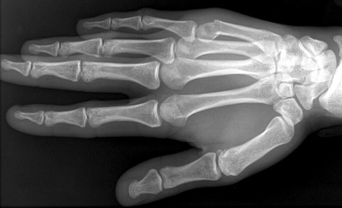
  • I broke my hand

    Winter can cruel here in Sweden.
    fraktur
    brutenhand
    Now I got to wear a cast for at least 4 weeks and then a plastic-support-thingie for another 2 weeks. Which means no flying for a long while 🙁