
It’s finally ready! Hydrogen balloons, fireworks and FPV, What more can you ask for in a video?
This has been by far the hardest video that I’ve made so far. So many things that went wrong or simply didn’t work. But I love a challenge. Minus degrees and snow didn’t put me of, those balloons had to be popped. (more…)
Author: RCExplorer – David
-
New video!
-
Hunting Hydrogen Balloons with Fireworks
- Airframe: Tricopter V2
- Stabilization unit: KK
- RC TX: Hitec Aurora 9 2.4GHz AFHSS
- RC RX: Hitec Optima 6
- Camera: Gopro Hero HD set at 720p 60FPS
- Video TX: 1.3GHz 300mW, 1/4 Lambda antenna
- Video RX: 1.3GHz with modified SAW filter
- Video RX antenna: 1/2 wave Dipole
-

Lost packet indicator
Many OSD’s has a RSSI (Receiver Signal Strength Indicator) input which measures voltage. Many FM receivers uses a chip that has an RSSI output which gives an analog signal that gets stronger the better reception you have. However many 2.4GHz receivers doesn’t have a RSSI output. I use Futaba’s FASST 2.4GHz system and the R617FS receivers does have a RSSI output. However this RSSI output is simulated and digitalized and isn’t that useful. Instead I found a much better way of telling how good reception I have.
The Futaba FASST 2.4GHz system like all 2.4GHz systems sends packets of information from the transmitter to the receiver. Each packet created follows a protocol and when the receiver receives a packet it checks that it intact, if it isn’t, it’s discarded. It only moves the servos if it receives a packet that is complete and valid.
The Futaba receivers have two led’s ether shines green of red. When the receiver is bound and receives good packets the led shines constantly green. But when the transmitter is turned of the led turns red. Hooking it up to an oscilloscope I discovered that every time it get’s a broken packet or no packet at all it sends a pulse to the red led making it blink. One packet lost gives a pulse of about 1-1.2ms. More packets lost equals a wider pulse which is great news! This means that you can with a simple RC-filter(resistor capacitor filter) can get a nice analog signal that increases in strength depending on the number of lost packets.
This is a much more accurate way of knowing your receiver signal health. An ordinary RSSI only displays how powerful the signal it receives is, not if it’s any good. Strong Interference shows as a high RSSI value while the receiver can’t “hear” your transmitter. With the lost packet indicator you know exactly how strong your RC link is regardless of interference.
In this guide I will be showing you how to modify the R617FS receiver, but this can easily be adopted for many other receivers. I do not know if other brands send a pulse to their led’s every time a packet is lost but if you got some “know how” you can easily find it out with an oscilloscope.

Here is a modified R617FS receiver. I drilled a small hole in the side of the case for the wire.
This is how simple it is. It’s just a wire soldered to the anode(+) of the red led.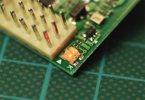
Coincidentally the arrow on the PCB points to precisely where you want to solder the wire to.The output from the LED is 1.8V. Now we need to make the digital signal from the led into an analog voltage, and to do that we need to construct a simple RC-filter(resistor capacitor filter). It’s nothing more than a resistor in series and a capacitor in parallel with the RSSI input. Here is a simple schematic:
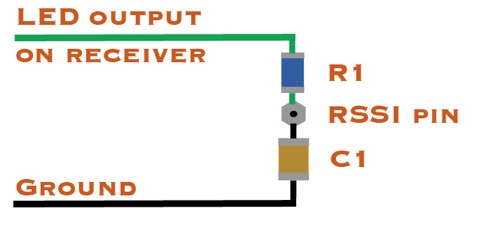
In simple terms, the resistor in series makes the capacitor charge slower than it normally would, it also makes the capacitor discharge at the same slow rate. Which means that the capacitor’s voltage rises almost linearly to the amount of pulses it receives.I found that around 70% lost packets the servos starts to get very jumpy. Above 30-40% lost packets and it’s time to head home. You can’t see of feel anything weird at that point but when you are loosing that many packets not much is needed to lose more, and it happens fast.
To know what resistor and capacitor to use, you need to do some math. I won’t be explaining how to calculate the values in this guide, but if you want to read about it, you can find it here; RC-Filters on wikipedia.
Since above 70% lost packets is almost the same as 100% when it comes to being able to control the aircraft, I decided to make the capacitor fully charged at about 70% duty cycle. This means that the OSD will read the 70% lost packets as 100%. Why do you want to do that? – You gain resolution in the spectra that is of use to you.I ended up with a 68K ohms resistor and a 10uF capacitor. Then when the OSD shows 50% lost packets it’s time to head home.
This is the OSD I will add the filter to, a Simple OSD from Flytron.com.

It’s important to have the filter as close to the OSD as possible, so I used SMD components and soldered them directly to the PCB.
The capacitor is a 1206 and the resistor is a 0805 which I had laying around.Here is a video where I use the lost packet indicator:
However I use different values in the video which results in a more “jerky” and less accurate readout. -
Secret project teaser
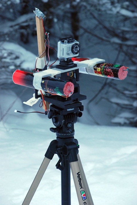
Here is a little teaser of what I’ve been working on the last week or so. I think you’ll enjoy it.
-
Tricopter V2 build log – Finished!
The Tricopter V2 build log is now completed!

And since you asked for it, I made PDF templates for the center plates for both the V1/V2 and V1.5. Simply download and print.
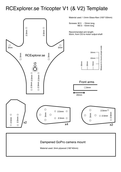
Be sure to post pictures if you build one. -
We have a winner!

Drumroll please…
The winner of the KK flight controller Give Away is…Mathew Wellington from New Zealand!
Congratulations Mathew! I hope you’ll share some pictures or video of your multi-rotor build.
I like to thank all of you that participated. Every cent donated to this Give Away will go towards making my next FPV video. Stay tuned and I don’t think you will be disappointed.
-
Want to win a complete KK flight controller? I’m giving one away!

I’m giving away a ready to install KapteinKUK multirotor flight controller. (more…)
-
New end-date on the Give-Away
I’ve changed the end-date on the Give-Away from the 19th of December to the 13th. I also wish to clarify that it ends at 23.59 GMT+1, as my distant friends will have to remember, there is a significant difference in time…
The reason for this is that I found out that if I mail the package before the 15th the winner will have it before Christmas. The winner will have to inform me what software to install before I send it, so therefore the Give-Away will end at the 13th.
Someone will have a merry Christmas!
-
Tricopter V2 Update
I just updated the Tricopter V2 build log. Now you can build your own KK controller.

Click here to get to the build log
