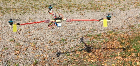
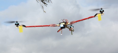
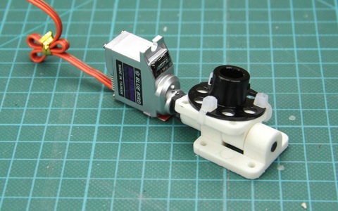
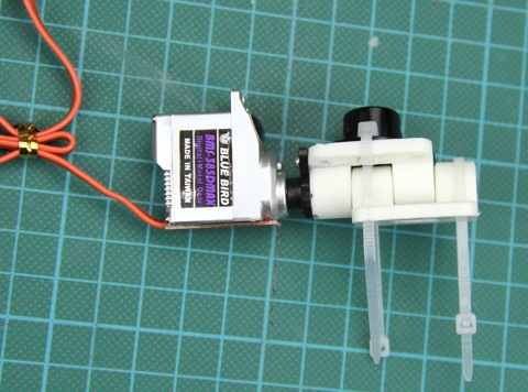
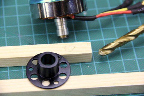
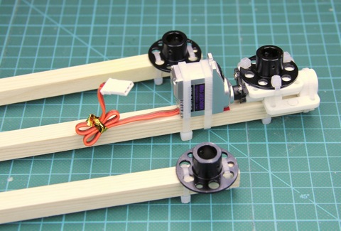
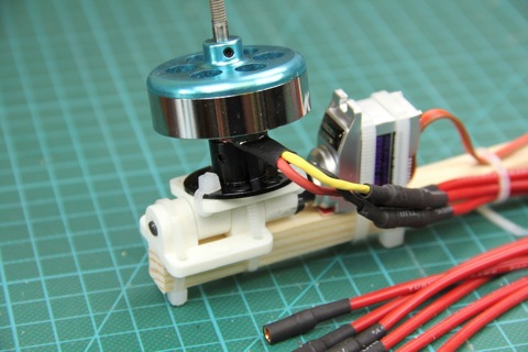
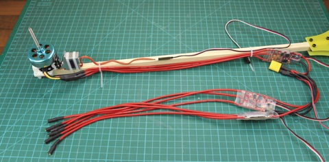
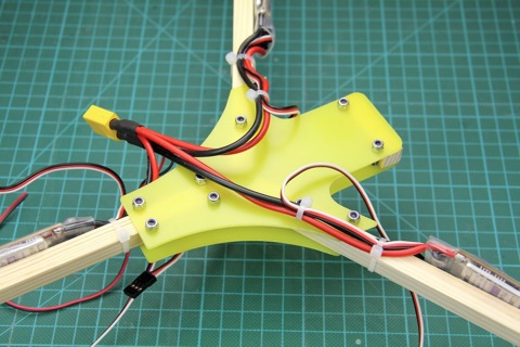
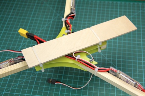
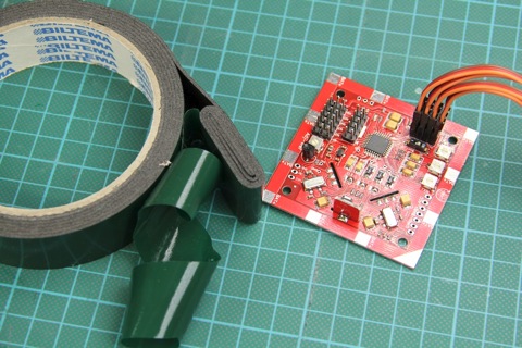
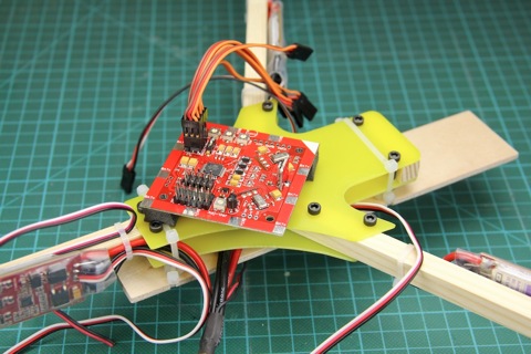
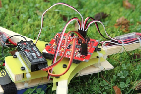
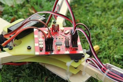
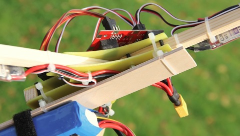
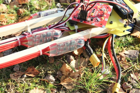
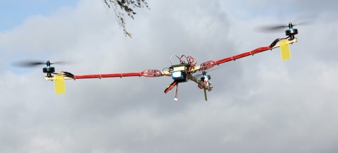
I have a few ”receiver ready” V2.5 Tricopters I’m now offering up for sale.
The Tricopters are built exactly like the V2.5 build guide.
All you need to do to make your first flight is to mount the landing gear using the included zip-ties, hook up your receiver, plug in your battery and check the stick direction. The Tricopter is already built, the gain is already set, the props are mounted and balanced, the gyro directions are already set up, the throttle range is calibrated, the ESCs are properly programmed and so on. I have test-flown them all and tuned them in accordingly.
The Tricopters also comes with two extra props (these have not been balanced, though) and one extra wooden arm for your first mishaps.
Things you need:
3s2200mAh Battery (Bigger battery is also ok)
4 channel (or more) receiver and transmitter
This is how you check if your transmitter sticks transmits the stick input in the correct direction:
– Turn on the transmitter and then the flight-controller
– Try arming the controller. (Move the throttle stick to the down-right corner) If the LED does not light up, reverse the rudder channel.
– Start the motors by raising the throttle (around 1/4 or so)
– Move the Pitch (Elevator) stick on the transmitter forward. The back motor should speed up. If it doesn’t, reverse the channel in your transmitter.
– Move the Roll (Aileron) stick to the right. The front left motor should speed up and the front right should slow down. If it doesn’t, reverse the channel in your transmitter.
-Done!
Do remember that these are KK-tricopters, no fancy auto-leveling and such, they don’t fly themselves. You have to learn how to do the flying.
So, would you want one of these limited numbers of Tricopters V2.5 built by RCExplorer? The price tag is 700600 USD and payment will be via Paypal (or bank transfer for Swedish buyers), shipping included (as a registered package with the Swedish Postal Services). When your order has been confirmed, you will have 7 days to complete the payment, so make sure that you can fulfill this requirement before you order, please. First come, first serve. Use the contact form and please write ”TRICOPTERORDER!” in the subject line to make sure that it isn’t lost in my messy inbox.
Update:
700 dollars did sound a little high, so I went back and recalculated all the expenses I had when building the Tricopters. I soon found my error, I had mixed up the currencies of one post. 100 SEK and 100 USD is big difference. The correct price for the tricopters should be 600 USD. I will refund a 100 USD to the people that have already ordered and payed. Sorry for the mixup guys.
Loads of people people have asked me if it’s possible to change the firmware on the Hobbyking KK board and thus making it possible use it on other platforms like the tricopter.
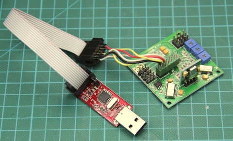
The answer is yes. It’s quite easy to do as well. All you need is an AVR programmer and to follow my new guide
Good luck!
This guide is made for the Hobbyking KK board V1 but will work just the same for the Hobbyking KK board V2, the only difference is that you have to select the correct board in the flash tool (The V2 uses a different processor). The V2 board is capable of running more advanced firmwares like the XX, where as the V1 is limited to the ”standard” firmwares.
The HK KK boards comes pre-flashed with the ”+” Quad KK firmware. In this guide we will change it to the Tricopter V1.6 firmware.
You need two things to change the firmware of the HK KK board:
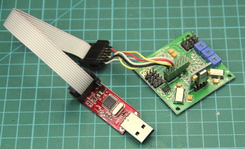
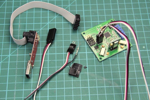
First thing is an AVR programmer. I use this AVR programmer from Flytron. But you can get one really cheap from Hobbyking or ebay. Search for ”usbasp” or ”AVR Programmer” and you’ll find loads.
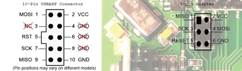
Second thing you need is an adaptor. Normally the AVR programmers comes with the standard 10 pin output, but the HK KK is 6 pins. Luckily the adapter is so easy to make that anyone can do it.
(Picture by arch001)
On the left you see the output from the 10 pin AVR programmer and on the left the 6 pin port of the HK KK board. All you need to do is connect the correct pins to each other. 1 to 9, 2 to 2, 3 to 7, 4 to 1, 5 to 5 and 6 to 10. (Picture by arch001) I soldered my own adapter but there is a simpler way that doesn’t require any soldering
That way is to use two servo extensions. Simply remove the protective plastic and pull the pins out.
Plug the pins into the connector in the right order and you’re done. Just make sure that the pins doesn’t touch each other. If you like to make the adapter reusable you can add some hotglue on the pins so that you don’t have to plug each pin in separately next time.
(Pin position in the picture is only for illustrative purposes)
Now that you have you’re KK board hooked up to the AVR programmer you need an AVR flashing software. There are a number of different options to choose from but I higly recommend using the KKmulticopter Flash tool. This software is specifically made to flash KK boards and is extremely simple to use. You don’t have to know about fuses or anything. The software even fetches the firmware file for you. And one of the best things, it works on both PC and MAC.
Install the proper drivers for your AVR programmer. If your on a mac and use a usbasp you don’t need to install any drivers.
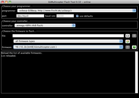
Launch the software
This is how it looks when you start it up. First thing you’re going to do is change the ”controller”
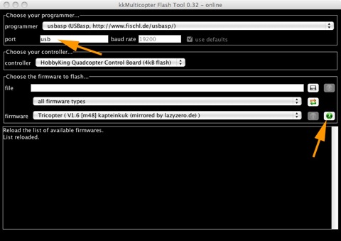
Choose the ”HobbyKing Quadcontroller” board from the list.
Choose the firmware you wish to use from the firmware drop-down list. The software automatically only shows softwares compatible with the controller you chose.
Change the port to ”usb” and make sure that the correct programmer is chosen in the top drop-down list. ”usbasp” is the default one.
Push the green ”go” symbol and sit back and relax while the software does the work for you. It takes about a minute to flash the board. Once it’s done the software will tell you: ”avrdude done. Thank you”
Thats it! You’re done. Unplug the programmer and go out and fly. Good luck!
Hi guys, sorry for not posting in a while. I’ve been ill this passed week, but now I’m fit for fight.
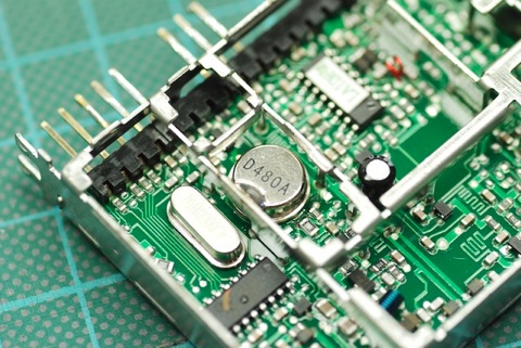
A while back I upgraded the SAW filter in one of my two lawmate receivers.
I have now done comparison between the modified and unmodified receivers.
The test was done over multiple flights with both receivers hooked up to a diversity switch (Eagle Eyes). Between each flight I swapped the antennas between the two receivers to eliminate that variable.
I wasn’t too surprised by the results. The modified receiver had better performance than the unmodified one, but not by a huge amount. Both receivers worked well but the modified one was nearly always chosen by the diversity switch. I didn’t really notice a huge boost in range but there was a slight improvement, I think. Maybe it’s just a delusion of mine. If you’re on the fence about exchanging the filter in you’re receiver but unsure if you’re really up to the task, I would recommend not doing it. The juice might not be worth the squeeze. However if you like modifying and soldering go right ahead. It does improve the performance and it’s kind of cool to have a modified receiver to boast to you’re friend about.
Ever since building the Tricopter V1 I’ve always tried to find ways to improve the construction. I always try new props, motors, esc’s, arm lengths, tail mechanism and such. Often I change stuff before each flight. Always in the quest to find the optimum setup for me.
The Tricopter V2.5 is more of an alternative to the V2 than something completely new. It uses different motors, speed controllers and tail assembly. There are also some minor changes to make the build a little easier and a little more crash resistant.
There is a new theme to the build: zip-ties. I love zip-ties. They make the build quick and easy. They break in a crash absorbing energy. These weak points are the key to the crash survivability of the tricopter. Rather than replacing a motor axel that has been bent, you simply replace a broken zip-tie. This can easily be done in the field as well.
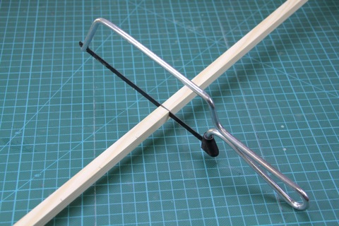
All three arms are the same length. I cut my arms to 48cm. The arms are 10*10mm pinewood.
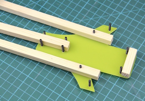
The holes in the front wooden arms are drilled 25mm from the edge. It’s slightly further in than the template states, but the extra material stiffens the frame a bit and is helps the durability. The little wooden piece in the front is 40mm long and helps stiffen up the frame considerably.
Time to screw the frame together.
I use these m3 lock nuts. Extend the arms fully before tightening. The arms are supposed to touch the screws when fully extended. Be careful not to over-tighten the screws, but they should be tight enough so that they do not move during flight. Now the main frame is done.
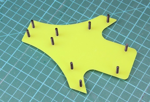
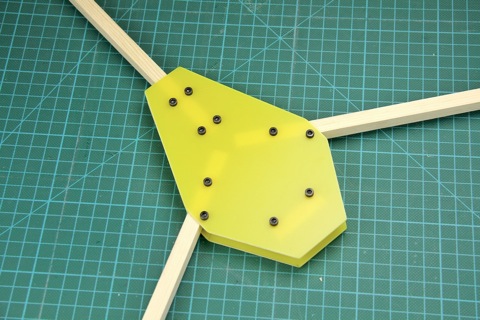
Here is a simpler alternative to the V1 templates. I call it the coffin body and it’s easier to make as all the lines are straight.
I made this coffin body slightly larger as the person I’m building it for needs the additional mounting surface.
Simply take the V1 template and draw straight lines instead of the curves and you’ll end up with the same shape.
Time to fix the ESC’s.
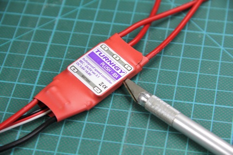
Off with the heat shrink.
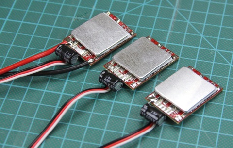
On two of the ESC’s, you should now remove all the cables except for the servo lead. On the third one, you should also keep the battery cables. This ESC will be the one on the tail and it just so happens that the cable is the right length to begin with.
New cables in place. Here are the cable lengths I used:
Back ESC battery cables: Stock (10cm)
Back ESC motor cables: 32cm
Front ESC’s battery cables: 18cm
Front ESC’s motor cables: 28cm
I used this 16AWG silicone cable.
Also soldered on 3.5mm bullet connectors.
New heat shrink. I used this nice transparent heat shrink that is nice and thick which helps protect the electronics. I have stripped the label from the original heat shrink, so that you can still identify the type of ESC’s, but this isn’t really necessary if you don’t want to. Looks nice though.
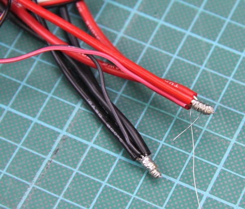
Time to solder the battery connector. (The thin extra wire is for powering FPV equipment) Here is a tip for soldering multiple cables:
Wrap a strand of wire tight around the exposed end. This holds all the cables in place during the soldering, reduces the size of the solder joint, and it also adds a mechanical bond to the solder joint.
Connector in place.
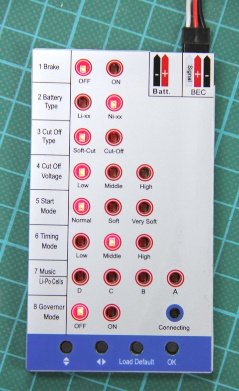
Now to the programming bit. I use this programing card. This is the settings I use on my ESC’s.
Now it’s time to make the new yaw mechanism. This is a bag of 40mm front wheel steering mounts. They are really inexpensive, one bag is enough for 2 and a half yaw mechanisms and costs under $2.5 here.
Take out two pieces.
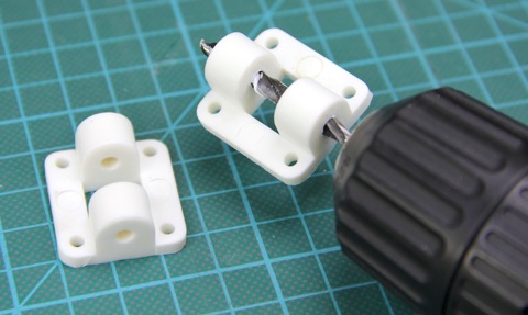
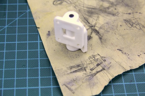
Start by drilling up the hole to 4.2mm of ONE (just one!) of the two pieces.
Remove any scraps of plastic after drilling the hole.
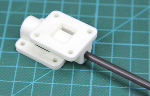
Place the pieces like in the picture and jam a 4mm rod through. It’s a tight fit in the piece that wasn’t drilled out, but that’s what we want. Use some muscles to get it through.
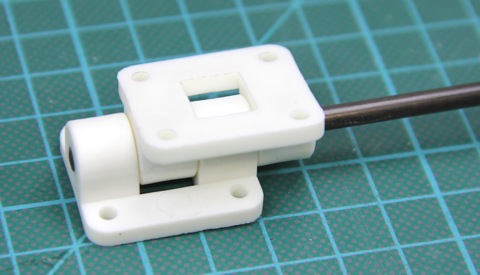
The rod should go all the way through but not poke out at the other end. I used a 4mm solid carbon rod to keep the weight down. The piece that was drilled out should move nice and smooth without any slop at this stage. If it’s not quite smooth, use an exacto knife or similar to wedge in between the two pieces and scrape a little to release pressure. Don’t remove to much though, you want a close fit.
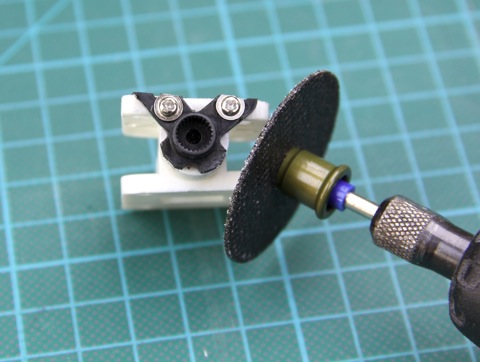
Cut the rod. I used a dremel with a cutting disc.
Done. It should pivot smoothly and without slop.
Sand the edge of the piece where the rod is stationary (the undrilled piece)
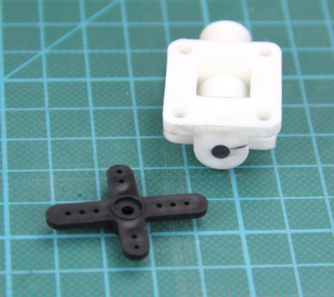
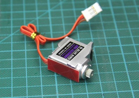
Time to connect the new yaw mechanism to the servo. The servo I use (BMS-385DMAX) comes with a cross shaped servo horn, which is perfect for this.
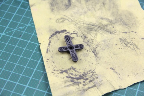
Sand the horn flat.
We’re going to drill two holes to fixate the horn, but to get good precision when doing this I recommend glueing the servo horn to the plastic using CA. Two things that is important; The servo horn should be mounted on the piece where the rod is stationary (the undrilled piece) and take great care to glue the horn in the dead center of the rod. If you’re off, there will be unnecessary strain on the servo.
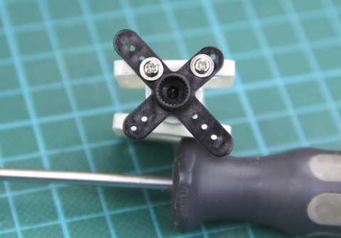
Drill two 1.5mm holes through the innermost holes on the servo horn. Drill as deep or a little deeper than the screw you’re using.
The screws I used came from a HXT900 servo. Nice size and I had tons of them laying around.
Cut off the excess plasic of the servo horn.
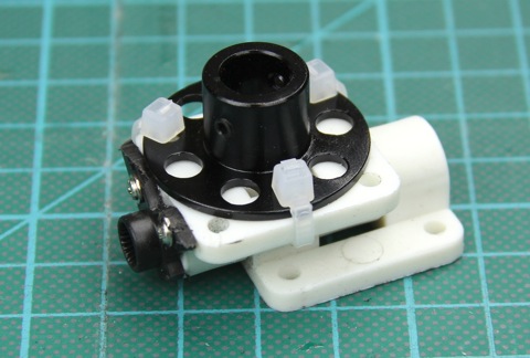
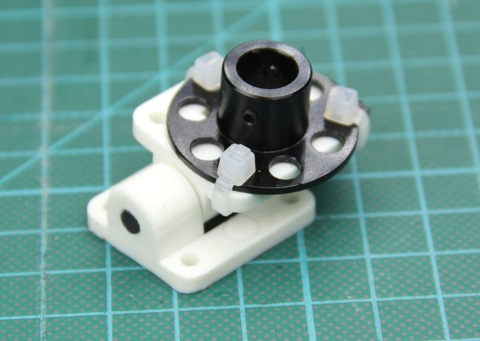
The DT750 motors comes with a mounting base which is the perfect size. You just need to drill one hole in the middle of one side on the piece that has the servo horn attached. To get the most maximum throw I highly recommend drilling the hole on the same side as I did (see picture). This way the zip-tie used to mount the motor base will not limit the travel in the direction that the mount is already leaning to compensate.
Three 2.5mm zip-ties is all that is needed.
The zip-tie that’s closest in the picture should be mounted just like in the picture, not to limit the travel (That is to say over the short edge).
The servo needs to be modified in order to be mounted properly. Cut off the bottom mounting ear flush to the case.
To get the correct hight I added a 0.8mm thick glass fiber piece to the bottom on the servo. You could just as easily sand down the plastic yaw-mount, if you don’t have anything laying around with the right thickness.
Yaw mechanism done!
Time to mount the yaw mechanism to the arm. Zip-ties for the win!
Mounted on the arm. The servo is mounted with bigger zip-ties.
When mounting stuff with zip-ties it’s a good idea to have the ”knots” in opposite directions if possible. This ensures that the thing you’re securing remains straight. Use a pair of pliers to really tighten all the zip-ties, as this is all that keeps your tricopter parts together.
Started soldering bullet connectors to the DT750 motors. I like the DT750’s. They are pretty efficient. They also have high torque due to their wide bell. This means that the prop will change RPM faster and the platform will be more stable and have a quicker response. I also like the 4mm threaded shaft as you can mount the props straight to the bell without any extra weight or hassle.
A weak point on these motors are where the windings meet the heat shrink. If you wiggle the cables back and forth too much the copper wires will fatigue and break. To fix that and make the motors more durable I added some epoxy.
The motor axel can extend a fraction of a mm out of the bottom of the motor mount base, and to prevent it rubbing against the arm I simply drilled away a tiny bit of wood underneath the mount.
If the motor rubs agains the arm it will draw more current and create more vibrations. Simply drilling a bit of the wood away is a quick and simple solution.
Mount the motor mount using 2.5mm zip-ties. Simple, cheap and fast. It also helps save the motors in a crash.
All the motor mounts mounted.
The axels on the DT750 motors are way to long stock. The risk of an axel getting crooked in a crash increases with the length. I cut mine down to 21mm. This is a good length for a GWS prop and lock nut.
Now it’s time to put the motors in place. Always use thread lock on all screws that goes into metal. Otherwise vibrations will loosen these screws over time.
Mount the back motor with the leads pointing 90° out from the arm. This will ensure that the cables won’t rub against the servo.
Landing gear mounted with zip-ties and prop mounted on the motor. The prop needs to be drilled to 4mm. I simply drilled it out with a power drill. Make sure to use lock nuts, otherwise the props will come loose over time. Also make sure not to over tighten the props. The bell can be pushed down to hard and create unnecessary friction agains the bearings.
This tail mechanism has low friction, little slop, is really sturdy and present very little added drag underneath the prop. The servo is mounted vertically in line with the arm and the tilt mechanism is hardly any larger than the bell of the motor. This means that more of the air the prop moves is used to actually lift the platform. I really like the direct drive servo as well. No slop or extra linkages.
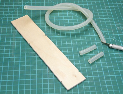
Next it’s time for a revised camera/battery mount. Notice the small slots. The original template can be found here.
For vibration dampening I used some silicone tubing I had laying around. The dimensions of the tube is 8mm outer diameter and 3mm inner diameter. I cut two 38mm pieces.
I used 2.5mm zip-ties (surprise!) to mount the tubes to the camera mount.
Bottom of the camera mount plate.
Bottom of the tricopter body.
Camera mount fixed to the tricopter body. Another pair of zip-ties, of course.
A more detailed picture of how the zip-ties are wrapped around the body to fasten the camera mount.
This means that the only connection between the body and the camera plate is through the silicone tubing.
I still love the KK board and I found a really ridiculous cheap one from Singapore for $25! These boards are no longer available with the tricopter V1.6 firmware, the price has also gone up. I now recommend getting this board from Hobbyking. It comes stock with a quad firmware and has to be reflashed with the tricopter V1.6 firmware, follow this guide. Update: I now recommend the KK2 board which doesn’t require to be reflashed, and it performs even better then the old KK boards.To mount the KK board, I use double sided sticky foam tape folded over 6 times and then cut into squares.
Simply peel off both sides and smack onto the KK board and you’re done.
Only needs a receiver and a battery now.
Done!
Folds up nicely for transport as well.
The new yaw mechanism works like a charm. I’ve had around 50 flights on it and so far so good. Still no slop and silky smooth.
Battery is held in place with a Scorpion battery strap which is awesome! It’s a little sticky and once it’s tight it won’t move anywhere. It just grabs that battery and holds it in place. Sorry for being so exited over a battery strap, but I’ve been looking for ever for a good battery strap and I finally found it.
Lift off.
One thing it does not lack is power. The DT750 motors are capable of lifting much more than the 2213N motors.
The DT750 motors runs smooth and quiet. Flight time is around 12 minutes with a 3s 2200mAh (without camera mounted).
Drumroll please!
Ladies and gentle men, I have the great pleasure to present the Tricopter V2.5!
The build log contains more than 80 pictures and I’ve tried to be as thorough as I could. My goal is that almost anyone should be able to build one.
Easy to build and very crash resilient, the Tricopter V2.5 is a great first step into the multirotor world. Click here to get to the build log!
Thanks for yet another great chat guys.
79 people turned up. The chat was pretty intense at times and the chat client didn’t quite hold up as well as I wanted it to. I’ll look into alternative clients when I get some time over. (more…)
Yay, I’m back! And what a trip it was. Here’s the full story (you’ll have to wait a bit for videos though):
I flew from Gothenburg to Amsterdam and then to Manchester. The airport security people are fascinated by me and my bag. It always gets two passes through the x-ray and then gets unpacked. They also seem to think that my batteries are dirty as they always wipe them with a tiny cloth (do they look that much like explosives?). But I never get any trouble. I simply explain what they are and why I need them and the always let me pass. (more…)
This coming Friday (the 9th) I’ll be in Blackpool, UK.
Discovery Channel has hired me to do some aerial work for their new series “PYROS”, which is a show about a professional pyrotechnics team that travels the globe to compete in the biggest firework shows.
I’ll be filming the crew as they set up, some general B-role of the area, the crowd and the final fireworks display.
I would love to have someone helping me out a little, assisting me as a spotter and as an extra pair of hands when they are needed. Would be great to have someone to talk a little RC with as well between the shots.
Anyone interested?
This past weekend I visited Sweden’s largest meeting with jet turbine powered models.
Over 25 models where flown. One to two models at the time were in the air and the sound and smell was awesome! (more…)