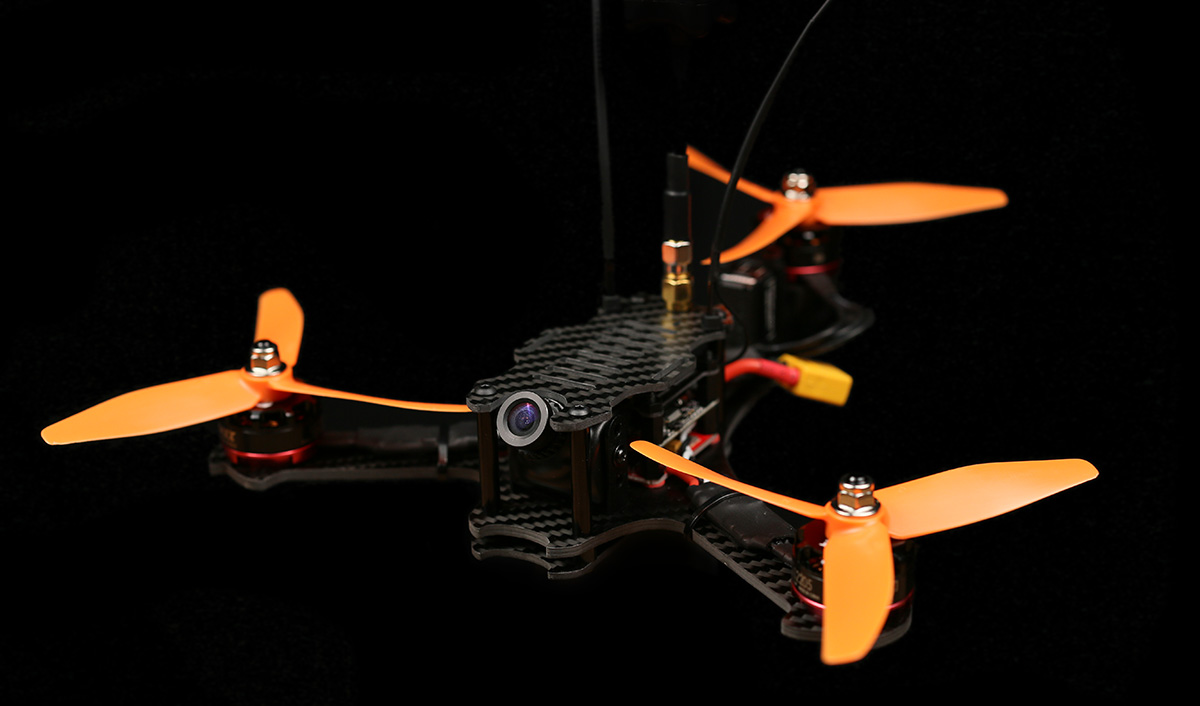
post

Baby Tricopter build

Baby Tricopter

Time to build a Baby Tricopter. This is a 170mm motor to motor crazy 7:1 thrust to weight ratio beast of a tricopter. It’s small and durable and a real blast to fly. So lets get started.

BabyTriBuild1

I’m going to built this baby tricopter (with F3FC + BabyPDB) together with the baby tricopter electronics pack.

BabyTriBuild10

Before we start mounting stuff, I highly recommend finishing off the carbon fiber in the kit. There is a crescent shaped diamond file included in the kit for this purpose. File the edges lightly. Wear breathing protection and be outside when doing this. Carbon fiber dust in pretty nasty stuff.
BabyTriBuild11

Be sure to get the holes as well.BabyTriBuild12

The reason why you should do this is mainly that the edges become smoother (duh), this keeps zip ties from snapping prematurely, tape wrapped around things last longer, battery/camera straps lasting much longer and recedes the chance of you cutting yourself when handling the copter.
BabyTriBuild2

Now we can mount the BabyPDB using the 10mm long nylon screws, fiber washers and standoffs.
BabyTriBuild3

The fiber washers are there to keep the BabyPDB from touching the frame. There is no exposed pads or anything on the bottom so it should be fine touching the carbon, but better be safe than sorry.BabyTriBuild4

Mount the board with the large pads towards the tail.
BabyTriBuild5

You’ll be needing a pigtail with the battery connector you plan on using. I’m using the 5cm XT60 pigtail, which I stripped back a bit to get more surface contact on the pads.
BabyTriBuild6

Soldered in place.
BabyTriBuild7

To get a bit more speed and torque from the BMS210 feedback servo, I bridged the 6V pads on the BabyPDB to get it to output 6V instead of 5V.
BabyTriBuild8

Screw the nylon standoffs down to hold the board in place.

BabyTriBuild9

Mounted in place. BabyTriBuild13

The wire on the BMS210 feedback servo is quite a bit too long, so we’re going to steal a piece to use to connect the PDB to the flight controller.BabyTriBuild14

That length looks about right.BabyTriBuild15

Strip and tin.
BabyTriBuild16

I connected the red wire to the BEC+ output, the brown to GND, the orange to ISENSE (current sensor) and the yellow to VBAT (raw battery voltage)
BabyPDB

Picture of the bottom of the PDB for reference.BabyTriBuild17

Solder the wires to the correct pads on the flight controller. The pads are quite clearly marked.

bec-5v

If you plan on powering anything power hungry through the flight controller I recommend moving this resistor over to the “BEC” position. This will bypass the built in 5V regulator on the flight controller. Instead the BEC voltage will power the board and all pads marked “5V” will output the BEC voltage.

So for instance if you plan on powering RGB LED’s through the board, I highly recommend doing this.
BabyTriBuild18

Now we’re going to do the tilt mechanism.BabyTriBuild19

If there is any hint of the tilt having any friction, lightly sand the pieces until it’s buttery smooth. BabyTriBuild20

If the screw is causing friction, try screwing it a ton of turns. The threads should wear down the plastic some and reduce the friction.
BabyTriBuild21

Strap down the tilt using two zip ties.BabyTriBuild22

Mount the zip ties so that the “knots” face the opposite direction.
BabyTriBuild23

Looks pretty good.
BabyTriBuild24

Mount the servo block in the grooves. If the block doesn’t sit all the way down flush, use the included file to remove a small amount of plastic. You want it to lay flat against the bottom.
BabyTriBuild25

Strap down the servo. You’ll be needing 2 zip-ties connected together to reach all the way around the servo. This also gives better strap down force as you have 2 places to apply force. Again alternate the “knots” not to get all force on one side. The groves for the tilt block extend backwards which will let you slide the servo back later when doing the servo alignment.
BabyTriBuild27

Time for the motors and speed controllers. BabyTriBuild28

The front two motors you can strip the wire really short for a clean and light setup. If you don’t like doing that you can always keep the long wires and fold them back over the ESC.BabyTriBuild29

Pretty clean.
BabyTriBuild31

Baby tricopter electronics kit include thick black heat shrink lined with a kind of hot glue. When shrunk the hot glue melts and if you squeeze the edges properly when the heat shrink is still hot, the ESC’s will be water resistant and very durable.
BabyTriBuild32

The back motor and ESC assembled a bit differently than the front 2.
BabyTriBuild33

The full length of the wires should be used, and they should be soldered on at an angle.
BabyTriBuild34

Shrink some heatsink over it and squeeze the edges.BabyTriBuild35

To screw down the motors use the included 6mm long screws. If you use longer screws you might damage the motor windings and smoke your motor and ESC. Always use blue locktite when screwing anything metal into metal.

BabyTriBuild37

I mount my motors using 2 screws instead of 4. This reduces the weight a bit. If the threads were to strip in a crash I can always mount the motors using the 2 holes that were unused before.BabyTriBuild36 BabyTriBuild38

One thing you really don’t want on any multi rotor is components moving around during flight, as this can create unwanted input to the gyro, making your copter fly bad.BabyTriBuild39

Double sided foam tape is a great thing to put underneath your ESC’s before strapping them down. It helps keep them in place as well as gives some dampening, which protects the ESC in a crash.
BabyTriBuild40

Strapped the ESC down with a zip tie. You can also use electrical tape or similar.BabyTriBuild41

Now mount the back motor.BabyTriBuild42

Screw it in place, but remember to mount it so that the wires comes out this way.BabyTriBuild43

For clarity, this is the way you want the wires to come out.
BabyTriBuild44

This is so that there is plenty of slack in the wire to allow for smooth, unhindered moment throughout the whole servo range. You can also see in the picture why we soldered the wire at an angle. Things get tight otherwise.BabyTriBuild45

Looks like a rats nest at the moment. We’ll start cleaning that up now.BabyTriBuild46

The back ESC should be soldered to the back ESC pads. Do not solder the ESC wires to the battery connector pads as this will bypass the current sensor and your current draw and mAh draw will be off by around 33%.BabyTriBuild47

The left ESC needs to have the red wire shortened and soldered to the + side of the PDB.
BabyTriBuild48

The right ESC is the opposite. The black wire needs to be shortened.
BabyTriBuild49

I’ll be using a X4R-SB receiver from FRSKY. I’ve removed the pins and directly soldered some servo wires to the SBUS output and kept the SPORT wire.
BabyTriBuild50

To protect the receiver I’m going to use some liquid electrical tape. It’s fantastic stuff which makes stuff water resistant and creates a rubbery kind of coating. If you plan on using it I highly recommend testing that the receiver works properly before putting the stuff on. It’s a real pain to get off. It’s also a good idea to take a picture of the top and bottom side of the board just in case something doesn’t work, you can go back and inspect your work.BabyTriBuild51

The reason why I’m using the X4R is that I had one laying around. If I would built another copter I would use the XSR receiver, which is smaller and lighter and fits in the stack without modification.BabyTriBuild52

Once dry I added some thin heat shrink.BabyTriBuild53

Will solder the receiver to the flight controller in a bit.
BabyTriBuild54

While we have good access to the power pins we might as well solder in the FPV system. I’m using a HS1177 camera and a Eachine TS5840 with a 90° antenna connector mounted on this build. Not super happy with this video transmitter though. Will probably switch it for a TBS Unify pro HV, which is a much better quality.
BabyTriBuild55

Soldered the signal wire between the camera and video transmitter.

I’ll be powering the camera via the 6V BEC on the BabyPDB. This will take load of the built in 5V regulator on the video transmitter, which will keep the video transmitter a lot cooler. The BabyPDB BEC also has a cleaner output as well as it protects the camera from voltage spikes. The video transmitter I’ll be powering straight from the flight battery.
BabyTriBuild56

I soldered the video TX + to the VBAT pad. The – to GND, the camera + to the BEC+ pad and the camera – to GND.

Schematic Video TX, cam, pub

Schematic. The reason why I don’t power the video transmitter from the built in BEC on the BabyPDB is that the minimum operating voltage on the videoTX is 7V. If you have a VTX that can handle 6V I recommend powering it from the BEC as it will significantly reduce the heat generated in the VTX.
BabyTriBuild57

It’s a great idea to have a beeper hooked up to your flight controller. This will greatly help when doing the tail tune and it will also help you find your copter when you crash it in tall grass and such.BabyTriBuild58

To keep things simple I decided to solder it straight to the board. You don’t have to do it this way. You can just as easily use some wire to get it away from the board.BabyTriBuild59

I bent the – pin of the beeper to 90° at the base and then 90° again further down to be able to reach the pads.BabyTriBuild60

Now we can start soldering signal wires to the board. The red and brown servo wires are connected to the pins on the edge labeled BEC + and GND. This will power the servo with the 6V from the babyPDB.BabyTriBuild61

The orange servo wire is soldered to the pad labeled number 2 and the yellow to the “FB” pad. If you’re using a servo that doesn’t have a servo feedback wire you only need to solder the servo signal wire to the “2” pad.BabyTriBuild62

Closeup of the soldering for extra clarity.BabyTriBuild63

Now the ESC wires. This is the way the signal wires should be connected:
Pad number 1 = Tail motor
Pad number 2 = Servo
Pad number 3 = Front Right motor
Pad number 4 = Front Left motor

F3FC Racing

F3FC Racing
BabyTriBuild64

All the black wires should be soldered to pads marked “-” This is important as the ESC’s might act weird otherwise.BabyTriBuild65

All hooked up.BabyTriBuild66

Time to connect the receiver. I connected my receiver in the following way; – to -, + to +, SBUS output to R3 (RX pin on UART3) and SPORT to T2 (TX pin on UART2). Also mount the nylon standoffs at this point.BabyTriBuild67

Some double sided foam tape to mount the receiver with. It’s also going to get squished down by the transmitter plate, holding it firmly in place.BabyTriBuild68

Mounted.BabyTriBuild69

Use a zip tie to mount the video transmitter to the transmitter plate.BabyTriBuild70

Mount the transmitter top plate using the M3 nylon nuts.BabyTriBuild71

Mounting the camera is really simple. The bracket that is included with cameras such as the HS1177 and the Runcam Swift fit into the milled down grove. This grove prevents the mount from turning and holds it firmly in place.BabyTriBuild72

Use a 6mm screw to mount it. If you’re using a Runcam swift use the 2mm screws that comes with it to mount it. You might need to file slightly on the HS1177 bracket as the manufacturing tolerances on those brackets are far from perfect.BabyTriBuild73

Use a m3 lock nut on the bottom.BabyTriBuild74

Look at that fanciness.BabyTriBuild75

The camera angle can easily be changed. If you think the angle is changed too easily you can always add some thin double sided tape on the inside of the bracket, but I’ve never needed it.BabyTriBuild76

The bracket really is super light and pretty a pretty clean solution.BabyTriBuild77

Now we’re going to mount the bottom and top plate.BabyTriBuild78

The kit includes some nylon standoffs. Place these over the 4 holes that are still unused.BabyTriBuild79

Place the bottom plate on top of them.BabyTriBuild80

Use the 14mm long screws and shove them through the spacers and the unibody frame.BabyTriBuild81

Screw on the 30mm aluminium spacers.BabyTriBuild82

Mount the top plate using 4 6mm long m3 screws.BabyTriBuild83

The top plate has slots in it to fit both GoPro and Runcam 2 form factor cameras. If you’re not running a camera on the top plate you can mount the battery there instead of on the bottom if you wish.BabyTriBuild84

Time to mount the antennas. To do this we’re going to use some good old zip ties.BabyTriBuild85

The top plate has slots for mounting these zip ties. Just slip them through and tighten them down.BabyTriBuild86

Closeup of the zip tie mounting.BabyTriBuild87

Slide over some heat shrink over both the zip tie and the antenna wire.
BabyTriBuild88

The heat shrink shouldn’t be too big. It should be able to shrink nice and snug around the zip tie and antenna.BabyTriBuild89

Shrunk down.BabyTriBuild90

Congratulations! The build is now done! Don’t forget to load the firmware onto the board and do all the setup. This process is the exact same as on the Tricopter V4 and Mini Tricopter, so you can look on the setup videos for either and set this thing up without any problem.

BabyTriBuild103

Also don’t forget to do the tail tune setup.
BabyTriBuild92 BabyTriBuild93 BabyTriBuild94 BabyTriBuild95

BabyTriBuild101 BabyTriBuild96 BabyTriBuild98 BabyTriBuild99 BabyTriBuild100

This is one crazy fast and super agile tricopter. I really look forward to seeing your builds and FPV videos! Please post them in this section of the forums. Good luck with your build!

Official release of Triflight 0.5

The Triflight 0.5 has moved out of the Beta stage. Now rebased on Cleanflight v1.13 which makes flashing easier. It also supports BLheli 4w interface for BLHeli passthrough among with many flight performance updates.

Here are some new features compared to Triflight 0.4

  • Rebased on Cleanflight v1.13.
  • Support for servo reversing (alpha)
  • Dynamic yaw output based on tail motor speed, replaces TPA for yaw (beta 3)
  • Tail motor acceleration/deceleration produced error estimation and correction (beta 3)
  • Support for wired servo feedback signal for accurate position measurement (beta 1beta 2)
  • Unarmed tail tune mode for setting up servo end-points, center position and speed calibration (beta 1)
  • More precise in-flight tail tune (beta 1)
  • Many small improvements.

Notes

  • Defaults are tuned for RCExplorer Baby tricopter (170mm sized). Should work okay for larger copters as well. Specific tunes for the Tricopter V4 and Mini Tricopter coming soon.
  • Display feature has been disabled for NAZE and CC3D targets due to memory constraints.
  • Best thing to do is a full chip erase doing flashing.
  • Please redo the servo setup / tail tune after flashing otherwise things might not work as they should.

We would love to get your feedback on how the official 0.5 release works for you. We’ve had great success with it so far. People have reported that the feel of this release has improved greatly and the tail handles even better.

Use the link below to jump over to the forum and give your feedback!

Triflight 0.5

We want happy pilots! – We urge you to use the support tickets for contact

We love hearing from you, but being stuck in a build or waiting for stuff or answers is never fun. For that reason we introduced the Support ticket system recently. The system makes sure that questions are filtered so they can be answered the fastest way possible – sometimes the answers can even be found within the FAQ it self to provide an instant answer that lets you continue your build or not having to wait for an answer, or your questions can be added to the FAQ for others to benefit from.

We have implemented this system as David’s inbox was overflowing and e-mails were being overlooked. Having Davids inbox as a single point of contract has turned out to be somewhat of a bottleneck resulting in unnecessary delays, you not getting any response, and claims regarding faulty/broken products, missing items etc to be made void. The support ticket system makes it easier for me to share the load of answering certain questions with David (so that he can focus on his areas of expertise), and to get a better overview of what has been done/said in each issue. This is especially important now that David is away. Please use the support ticket system, we want happy pilots 🙂

Regards,
Johanna

Pre-Release of the BabyTricopter is… NOW!

With David all the way across the big pond meeting some of you at FliteTest, this announcement has fallen on my shoulders, and will therefore be shorter and less descriptive than usual. Here goes:Baby Tricopter


Baby TricopterA new beast has hatched. Measuring 170mm motor to motor and weighing only 280 grams with electronics and FPV gear, the BabyTricopter is in size and weight really just a baby compared to its older brothers. But don’t be fooled, this baby packs a punch! Be sure that you know what you’re doing before flying this beast…

You can choose between the Baby with it’s custom F3FC racing and power distribution board included for just $99, or  just the Baby Tricopter (without flightcontroller and PDB), for as little as $69.

The F3FC Racing and new PDB can of course
also be bought separately (although you get a nice discount if you buy them with the kit), and you’ll find more info on those product pages.

Shipping will start on Monday/Tuesday so order now!


The Baby of course will need some power, and we’re also releasing an electronics kit, with the same EMAX motors as used by the MiniTricopter, but with Aikon 30A ESC’s and three-bladed orange propellers from HQ. This kit is however currently on Pre-Order, ar we are awaiting the arrival of our chosen Aikon 30A ESC’s. You can still order the kit, but it won’t be shipped until the ESC’s have arrived.


Have some patience with the product descriptions and info, this is, after all, a Pre-Release! More info will be added, and spare parts will become visible in the store as we’ve had time to somewhat fix their respective product pages.

Out of office – Limited support and email replies for a while

I’ll be jumping on a plane headed for Flite Fest tomorrow morning. During my stay I’m going to have limited internet access and time to answer emails and such. Johanna will be holding down the fort while I’m gone, answering support tickets and shipping out orders just as usual.cropped-FF16_logo_horizontal-01I know I’ll be seeing some of you at Flite Fest. It’s going to be an awesome time! Just hope the Ohio weather cooperates.

After Flite Fest I’ll be joining the RotorRiot crew in Pripyat, Ukraine to do some flying. This means that if you send me an email, you shouldn’t expect a reply until August.

Lowering aesthetic standard (and price) on the carbon fiber arms

Some of you might remember my everlasting battle with manufacturing of the carbon fiber arms. There is a reason why most companies I’ve approached have declined to even try making them. 10x10mm woven square tubes are really difficult to make. Extruded tubes this size is no problem, but they really suck. The arms we sell now are fantastic when it comes to strength, weigh, stiffness and have no warp.

The problem is that the surface finish is almost impossible to get perfect. So far we’ve discarded large parts of batches due to these imperfections and it’s really not sustainable. We at least need to break even on the arms. That would mean either almost doubling the price or lowering the standards, or stop selling them altogether.

Right now the most reasonable thing seems to be lowering the cosmetic standards in our quality checks. To be clear; only the surface finish is effected. The structural integrity and function is unaffected and the arms will be just as strong as before. The difference is that you might get arms that are scratched, have small dimples, have a visible edge of the carbon or other cosmetic impurities. Again, this will not effect the function or performance of the arms.

Since you will now receive a lower quality product we feel that to be fair we should lower our prices. The 325mm arms are lowered by 1USD and the 162.5mm by 0.5USD.

How do you feel about this?

New FAQ and support system

We’ve been testing out a new support system for a while and it’s now time to start using in for real. You will now be able to open a ticket by either going to your account page, or by clicking the FAQ/Support meny tab in the top navigation bar. This system will allow us to help you more efficiently and with less risk of your email getting lost in the river of messages that is my inbox.

The FAQ portion of the page is filled with the most common questions we get. Please at least skim it before opening a ticket.

If you want to contact me directly with stuff that isn’t related to orders or support stuff you can still use the contact from on the “about us” page. But please understand that I might not always answer as I get quite a few. You do not need to have an account registered in order to open a ticket.
Just make sure that you spell your email address correctly, or we won’t be able to answer you. If you have an account you can easily see all your tickets and open new ones from your account page.

We hope this system will let us help you in a more efficient way.